www.soundskulptor.com
Document revision 1.3 – Last modification : 28/02/20
MP 566 Assembly guide – Main PCB, A side
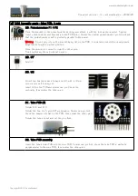
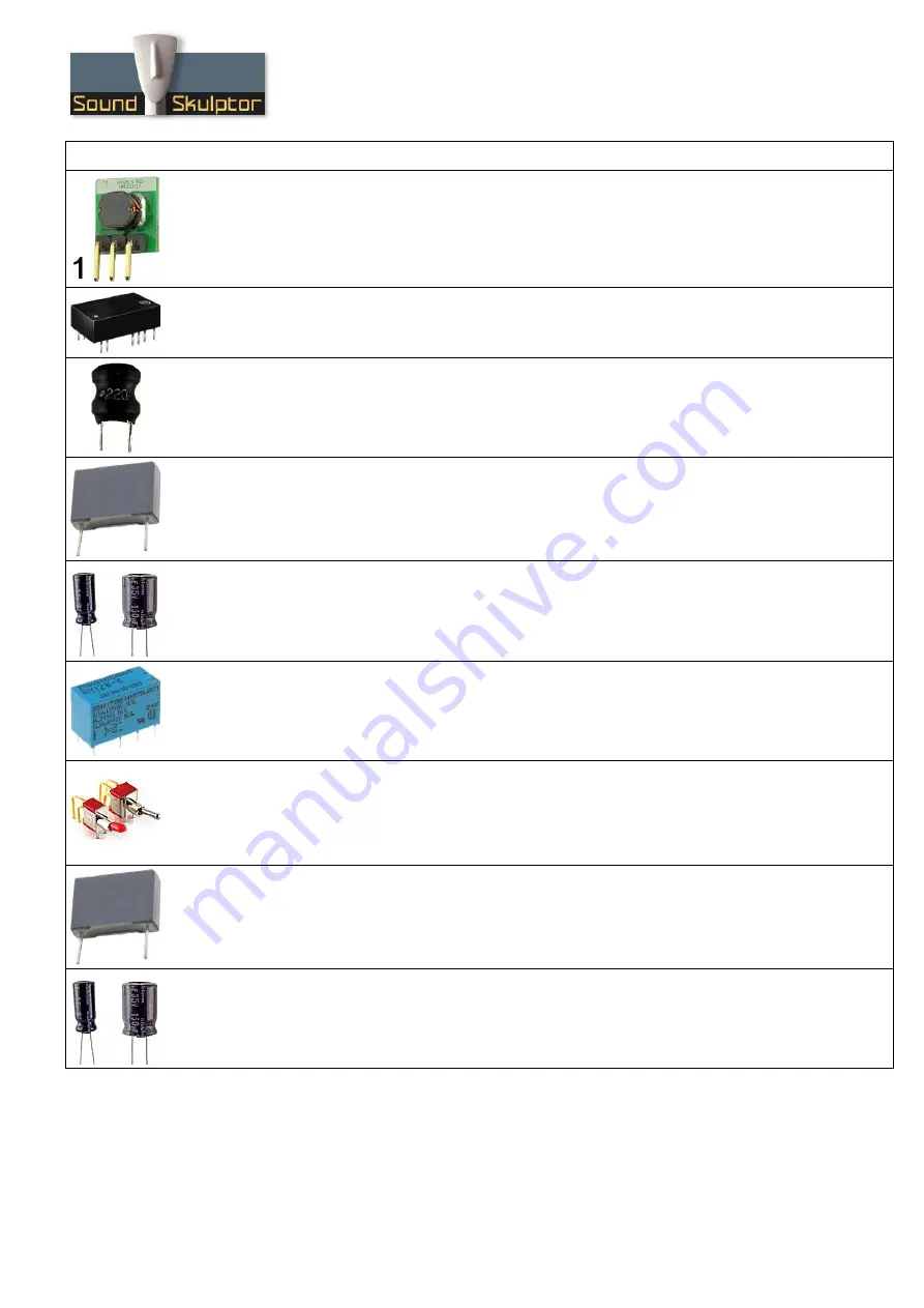
19. U6
Insert and solder U6.
Warning
: Do not reverse. Pin 1 is identified by a white dot on the PCB.
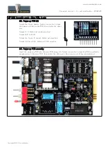
20. U5
Insert and solder U5.
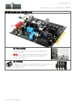
21. Radial inductors
Add L1, L2.
22. Medium size film capacitor C6
Add C6.
23. Small electrolytic capacitors
Add C11, C13, C14, C26, C27, C28.
Solder one lead first, adjust verticality then solder the second lead.
Warning
: The +lead must go into the +hole. Do not reverse (they may explode !)
24. Relay
Add RLY1 and RLY2.
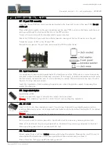
25. Switches
Add SW1, SW2 and SW3. The position of the switches is critical for a good front-plate matching. They
must sit flat on the PCB. Press firmly the switch on the PCB and solder one of the front pins (housing).
Check verticality and horizontality. Then solder the other pins.
26. Large size film capacitors
Add C9 and C10.
27. Medium size electrolytic capacitors
Add C1, C5, C7, C4.
Solder one lead first, adjust verticality then solder the second lead.
Warning
: The +lead must go into the +hole. Do not reverse (they may explode !)
Copyright ©2015 SoundSkulptor


