


15
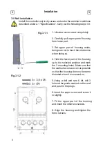
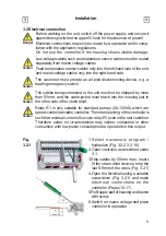
3.2 Electrical connection
(continued)
Installation
3
3
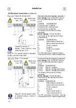
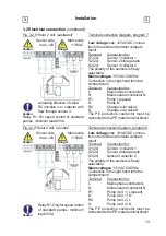
Fig. 3.2.12 “Solar with follow-on storage
tank/Solar & transfer“
Terminal connection diagram,
program 11
Low voltage
max. 12VAC/DC connec-
tion in the left-hand terminal compart-
ment!
Terminal: Connection
for:
S1 (2x)
Sensor 1 collector
S2 (2x)
Sensor 2 storage tank 1
S3 (2x)
Sensor 3 storage tank 2
Sensor side
max. 12V
Danger
Caution
Mains side
115VAC
The polarity of the sensors is freely
selectable.
Mains voltages
115VAC 50-60Hz
Connection in the right-hand terminal
compartment!
Terminal: Connection
for:
L
Mains phase conductor L
N
Mains neutral conductor N
R1
Pump L (speed)
N
Pump N
R2
Pump (storage tank 2) L
N
Pump (storage tank 2) N
The PE protective conductor must be
connected to the PE metal terminal block!
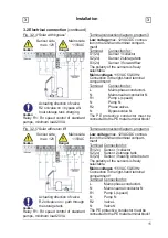
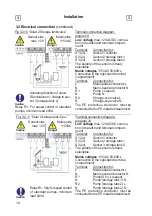
Terminal connection diagram,
program 12
Fig. 3.2.13 “Solar with swimming pool and
heat exchanger”
Low voltage
max. 12VAC/DC connec-
tion in the left-hand terminal compart-
ment!
Terminal: Connection
for:
S1 (2x)
Sensor 1 collector
S2 (2x)
Sensor 2 swimming pool
S3 (2x)
Sensor 3 forward
fl
ow
The polarity of the sensors is freely
Caution
Relay R1: Only for speed control
of standard pumps, minimum
load 20VA
selectable.
Mains voltages
115VAC 50-60Hz
Connection in the right-hand terminal
compartment!
Terminal: Connection
for:
L
Mains phase conductor L
N
Mains neutral conductor N
R1
Pump, prim. L (speed)
N
Pump, primary N
R2
Pump, secondary L
N
Pump, secondary N
The PE protective conductor must be
connected to the PE metal terminal block!
Sensor side
max. 12V
Caution
Mains side
115VAC
Caution
Relay R1: Only for speed control
of standard pumps, minimum
load 20VA
Danger


