


12
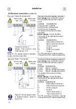
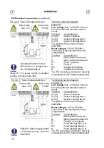
3.2 Electrical connection
(continued)
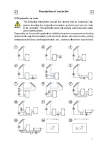
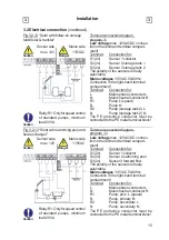
Installation
3
3
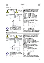
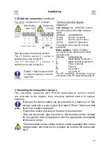
Fig. 3.2.6 “Solar with
2 zone storage tanks”
Terminal connection diagram, program 5
Low voltage
max. 12VAC/DC connec-
tion in the left-hand terminal compart-
ment!
Terminal: Connection for:
S1 (2x)
Sensor 1 collector
S2 (2x)
Sensor 2 storage tank below
S3 (2x)
Sensor 3 storage tank above
Sensor side
max. 12V
Danger
Caution
Mains side
115VAC
Caution
The polarity of the sensors is freely
selectable.
Mains voltages
115VAC 50-60Hz
Connection in the right-hand terminal
compartment!
Terminal: Connection for:
L
Mains phase conductor L
N
Mains neutral conductor N
R1
Pump L (speed)
N
Pump N
R2
Zone valve L
N
Zone valve N
The PE protective conductor must be
connected to the PE metal terminal block!
Relay R1: For speed control of standard
pumps, minimum load 20VA
Actuating direction of valve:
R2 on/valve on = charge to sen-
sor 3 (storage tank above)
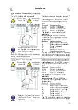
Terminal connection diagram, program 6
Fig. 3.2.7 “Solar with ext. heat exchanger”
Low voltage
max. 12VAC/DC connec-
tion in the left-hand terminal compart-
ment!
Terminal: Connection
for:
S1 (2x)
Sensor 1 collector
S2 (2x)
Sensor 2 storage tank
S3 (2x)
Sensor 3 forward
fl
ow
Caution
Relay R1: Only for speed control
of standard pumps, minimum
load 20VA
The polarity of the sensors is freely
selectable.
Mains voltages
115VAC 50-60Hz
Connection in the right-hand terminal
compartment!
Terminal: Connection
for:
L
Mains phase conductor L
N
Mains neutral conductor N
R1
Pump, secondary L (speed)
N
Pump, secondary N
R2
Pump, primary L
N
Pump, primary N
The PE protective conductor must be
connected to the PE metal terminal block!
Sensor side
max. 12V
Danger
Caution
Mains side
115VAC


