background image

46

Playback

  C
h

ap
te

r 4


R

e

c

o

rd

in

g,

 P
lay
ba
c

k

 an
d

 C
o

p

y

Shot marks cannot be set to a locked clip.

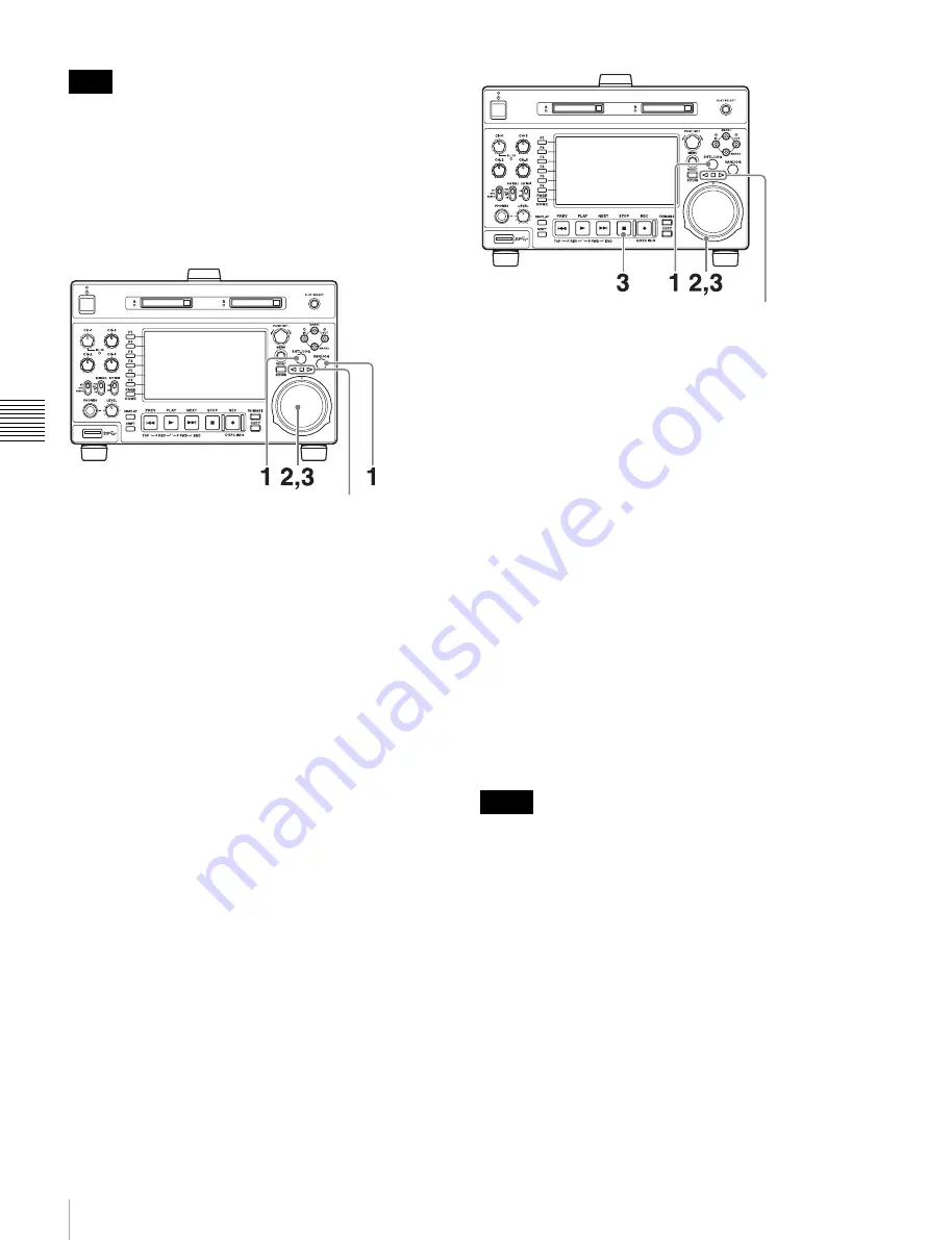
Playback in jog mode

In jog mode, you can control the speed of playback by the 
speed of turning the jog dial. The playback speed range is 
–1 to +1 times normal speed.
To carry out playback in jog mode, proceed as follows.

1

Press the SHTL/JOG button or VAR/JOG button, 
turning it on.

2

Turn the jog dial in the desired direction, at the speed 
corresponding to the desired playback speed.

Playback in jog mode starts.
The Jog/shuttle transport indicators light as follows.

b


(green):

 Lights during playback in the reverse 

direction.

B


(green):

 Lights during playback in the forward 

direction.

3

To stop playback in jog mode, stop turning the jog dial.

When setup menu item 101 SELECTION FOR 
SEARCH DIAL ENABLE is set to “dial” (factory 
default setting), you can start jog playback by simply 
rotating the jog dial, even when the SHTL/JOG and 
VAR/JOG buttons are not lit.

Playback in shuttle mode

In shuttle mode, you can control the speed of playback by 
the angular position of the shuttle dial. The range of 
playback speed is ±20 times normal speed or maximum 
speed. 
To carry out playback in shuttle mode, proceed as follows.

1

Press the SHTL/JOG button, turning it on.

2

Turn the shuttle dial to the desired angle 
corresponding to the desired playback speed.

Playback in shuttle mode starts.
The shuttle dial has a detent at the center position, for 
still image playback.
The Jog/shuttle transport indicators light as follows.

b


(green):

 Lights during playback in the reverse 

direction.

B

 (green):

 Lights during playback in the forward 

direction.

x


(red):

 Lights during still image display.

3

To stop playback in shuttle mode, return the shuttle 
dial to the center position, or press the STOP button.

When setup menu item 101 SELECTION FOR 
SEARCH DIAL ENABLE is set to “dial” (factory 
default setting), you can start shuttle playback by 
simply rotating the shuttle dial, even when the SHTL/
JOG button is not lit.

• When setup menu item 101 SELECTION FOR 

SEARCH DIAL ENABLE is set to “dial”, after using the 
shuttle dial, return it to the center position. If the shuttle 
dial is not in the center position, it is possible 
occasionally for vibration from other operations to 
activate the dial, and start playback in shuttle mode.

• When you play back a clip without proxy AV data in 

shuttle mode, the output video and audio will be 
discontinuous.

To alternate between normal-speed playback and 
shuttle mode playback

Set the shuttle dial to the position corresponding to the 
desired shuttle playback speed, then switch between 
normal-speed playback and shuttle playback by pressing 
the PLAY and SHTL/JOG buttons alternately.

Note

Jog/shuttle transport 
indicators

Notes

Jog/shuttle 
transport indicators

Summary of Contents for XDCAM PMW-1000

Page 1: ...MEMORY RECODER PMW 1000 OPERATION MANUAL English 1st Edition ...

Page 2: ...ser and non Sony nonlinear editors 23 Connections for cut editing 24 Using the editing functions of the recorder controlling through REMOTE 9P connector 27 Connections for pool coverage 28 Synchronization Reference Signals 29 Setting System Frequency 30 Setting Timecode 30 Superimposed Text Information 32 Basic Operations of the Function Menu 34 Function menu operations 34 Function menu settings 3...

Page 3: ...g thumbnails 47 Copying 48 Overview 48 Copy operations 48 Chapter 5 Operations in Clip List Screens Overview 51 Switching between display screens 51 Information and controls in clip list screens 52 Clip Menu 55 Clip F Menu 56 Clip Operations 57 Selecting clips 57 Searching with thumbnails 57 Playing a clip by thumbnail search 58 Setting clip flags 59 Locking write protecting clips 59 Deleting clip...

Page 4: ...nk operations menu items B01 to B13 78 Items in the extended menu 79 Appendix Important Notes on Operation 90 About the LCD panel 90 Periodic Maintenance 91 Operating hours meter 91 Troubleshooting 92 Alarms 92 Error messages 97 Specifications 98 Using UMID Data 102 Ancillary Data 104 Ancillary data in HDSDI SDSDI signals 104 Ancillary data in MXF files 104 Closed caption data 105 Trademarks and L...

Page 5: ...Table of Contents 5 Character display software iType 106 Open software licenses 106 Obtaining GPL LGPL GPL V3 licensed software 107 Index 108 ...

Page 6: ...100 in 1080i 1080 effective scanning lines format Uncompressed PCM recording of 24 bit 48 kHz audio enables 8 channel audio recording at high sound quality Recording and playback functions Support for MPEG XAVC SD with multiple codecs In addition to the MPEG HD422 codec and XAVC MPEG 4 AVC H 264 codec CLASS 100 this unit supports the MPEG HD420 codec allowing HD operation across a wide range of re...

Page 7: ...r is not available for example outdoors or in cars or helicopters 1 BKP L551 Battery Adaptor is required Color LCD display The unit is equipped with a 16 9 4 3 inch color LCD which allows you to check the contents of the SxS memory card and use the menu system without connecting an external monitor Built in speakers The unit features built in speakers allowing you to check recorded audio You can c...

Page 8: ...HDW 2000 series only PDW 700 PMW 500 RM 280 editing controller BVE 700 Headphones HDW 2000 series PDW F75 SxS memory cards PDW 1500 BP L80S Battery Pack BKP L551 battery adaptor DC power source AC power source SD video monitor HD video monitor Audio monitor Laptop computer ...

Page 9: ...indicator lit red and holding it down for a short time 0 25 seconds or longer the indicator changes to lit green and the unit enters the operating state When you press this button with the indicator lit green and holding it down for a longer time 1 second or longer the indicator changes to flashing green and then lit red and the unit enters the standby state When using this unit normally leave the...

Page 10: ...HOME page of the function menu see page 34 e LEVEL volume adjustment knob Adjust the volume of headphones or speakers with the knob You can also cause this to simultaneously adjust the output volume from the AUDIO MONITOR R L connectors on the rear panel To do this set setup menu item 114 AUDIO MONITOR OUTPUT LEVEL to var f Super Speed USB connector USB 3 0 Connect the USB connector of the externa...

Page 11: ...to set the OUT point before a recorded IN point this flashes c B IN button and b OUT button When the the clip list screen is shown on the display you can use these for thumbnail selection An IN or OUT point is set when you press the PUSH SET knob with the B IN or b OUT button held down The IN or OUT point setting is deleted when you press the RESET RETURN button with the B IN or b OUT button held ...

Page 12: ...tches the display screen between thumbnails view and details view i SHIFT button Switches between functions for any button with two functions j PAGE HOME button When pressed alone functions as the PAGE page switching button When pressed together with the SHIFT button functions as the HOME button PAGE button Displays the function menu if it is not already visible The most recently displayed page of...

Page 13: ...n to the original video You can also press this button during playback and searches EE mode playback continues for as long as the button is held down f REC INHI recording inhibit indicator This lights when an SxS memory card with recording inhibited or a non recordable media is loaded Display screen Basic operation screen a Function menu Use the PAGE HOME button to display this menu and to switch ...

Page 14: ... SD format reference signal B Video input display This displays the selected video input signal HD SDI HDSDI video input SD SDI SDSDI video input SG Test video signal from the internal signal generator The video signal input is selected with V INPUT on page P1 INPUT of the function menu see page 35 The display blinks when there is no video input signal and when the video input signal does not matc...

Page 15: ...ottom row G DF NDF indication Displays the frame count mode for the internal timecode reader TCR and internal timecode generator TCG The frame count mode is set with DF NDF on page P4 TC of the function menu see page 36 i Status display area A Error warning and alarm messages Messages about operations and the status of the unit appear here The seriousness of the message is indicated by the color a...

Page 16: ...TERY END VOLTAGE the unit is automatically shut down Video monitor screen A Superimposed information Appears when CHAR SEL on the HOME page of the function menu is set to ON B Status display area Displays messages and icons about the status of the unit see page 15 You can disable the status display area with the DISPLAY button However it is automatically enabled when Display of error warning alarm...

Page 17: ...ge 75 for more information about the setup menu item 028 HD CHARACTER To treat the input and output signals of these connectors as non audio signals set a maintenance menu item For details refer to the Maintenance Manual d SDSDI OUTPUT 1 2 SUPER SDI signal outputs 1 2 superimpose connectors BNC type These output SDSDI format video audio signals When the unit is shipped from the factory audio signa...

Page 18: ... connector for peripheral device wiring that might have excessive voltage to this port Follow the instructions for this port When you connect the LAN cable of the unit to peripheral device use a shielded type cable to prevent malfunction due to radiation noise k MAINTENANCE connectors These are the High Speed USB USB2 0 connectors for maintenance 1 Power supply section a POWER main power switch Pr...

Page 19: ...ectors XLR 3 pin male This outputs an audio signal for monitoring The monitored channel is selected with MONITR L and MONITR R on the HOME page of the function menu See Basic Operations of the Function Menu page 34 for more information about the MONITR L and MONITR R settings 3 Timecode input output section a TIME CODE IN connector BNC type This inputs an SMPTE timecode generated by an external de...

Page 20: ... Battery Adaptor and a BC L100 Battery Charger are also required Continuous recording time at room temperature BP L80S lithium ion battery pack Approx 80 minutes For details on charging battery packs refer to the operation manual for the battery charger Notes about battery usage As long as a battery is connected to the unit electric current flows in the unit to keep the CPU in the standby state ev...

Page 21: ... to the DC IN 12V connector Removing the battery pack With the lever pushed in slide the BP L80S out as shown below Checking the remaining battery power You can use the LEDs on the side panel of the battery to check the remaining power of the battery When the remaining battery power decreases substantially and the voltage approaches the set shutdown voltage the power source icon starts flashing in...

Page 22: ...y UC for regions outside Japan or J for Japan and then press the SET function button F5 The system frequency screen appears 3 Turn the PUSH SET knob to select the system frequency Display the system frequency that you want to use and then press the SET function button F5 The recording format selection screen appears 4 If you want to save the settings made up to this point press the SET function bu...

Page 23: ...connector FTP connection The following shows an example of an FTP File Transfer Protocol connection The PMW 1000 IP address and other network related settings are required for connection For details of the network related settings refer to the Maintenance Manual Connecting this unit directly to a laptop computer Connecting three PMW 1000 units to a laptop computer via a LAN When you connect the Ne...

Page 24: ...0P unit as a recorder and a BVE 700 700A as an editing control unit HD video monitor To HDSDI input connector 1 75Ω coaxial cable not supplied 2 9 pin remote control cable not supplied PMW 1000 this unit player Reference video signal HDW M2000 recorder To HDSDI input connector HD video monitor BVE 700 700A editing control unit To HDMI input connector a 3 HDMI cable not supplied Recommend to use an...

Page 25: ...see page 10 REF VIDEO INPUT connector 75 Ω termination switch OFF Setup menu item 214 REMOTE INTERFACE 9PIN Audio selection function switching button INPUT button HDSDI Function menu HOME F1 VID IN SDI Function menu page 1 F1 TCG INT Function menu page 1 F2 PR RGN PRESET Function menu page 1 F3 RUN FREE System frequency VTR constant 1 2 3 4 5 6 7 8 9 10 11 12 13 14 15 16 59 94i 59 94P 29 97P A0 B1...

Page 26: ...trol cable not supplied PMW 1000 this unit player Reference video signal PDW F1600 recorder To HDSDI input connector RM 280 editing controller HD video monitor To HDMI input connector a 3 HDMI cable not supplied a You can use setup menu item 161 see page 80 to set which signal to output from the HDMI OUT connector the same signal as the HDSDI OUTPUT 2 SUPER connector output or the HDSDI signal and...

Page 27: ...ge P1 VIDEO V INPUT HD SDI Setup menu 05 SYNC SEL ON Function menu pages P2 and P3 AUDIO A1 to A8 INPUT SDI Setup menu 06 SYNC VTR RECORDER Function menu page P4 TC TCG INT Setup menu 09 EDIT DLY 7 Function menu page P4 TC PRST RGN PRESET Setup menu 10 R ST DLY AUTO Function menu page P4 TC RUN MODE FREE RUN Setup menu 11 P ST DLY AUTO HD video monitor To HDSDI input connector PMW 1000 this unit p...

Page 28: ...r connected HDW M2000 recorder setting Settings on this unit REMOTE 1 9P button Unlit Remote control switch REMOTE see page 10 Setup menu item 214 REMOTE INTERFACE 9PIN 75Ω coaxial cable not supplied To SDI OUT 1 connector PDW 700 PMW 1000 this unit To SD HDSDI INPUT connector PDW 700 camcorder setting Settings on this unit HDSDI REMOTE I F on page CAM CONFIG 1 of the MAINTENANCE menu other than O...

Page 29: ...he HOME page of the function menu to REF and synchronize the synchronization reference signal generator of this unit to a reference signal input to the REF VIDEO INPUT connector The following reference signals can be used 720 59 94P system 1080 59 94i tri level sync signal 525 black burst signal 720 50P system 1080 50i tri level sync signal 625 black burst signal When you directly interconnect vid...

Page 30: ...rnal timecode generator set beforehand to an initial value The following run modes can be selected Free Run Timecode advances continually Rec Run Timecode advances only during recording Internal Regen regenerate mode This records the output of the internal timecode generator initialized to timecode following continuously upon the timecode of the last frame of the last clip on the SxS memory card E...

Page 31: ...n hexadecimal 0 9 A F You can record ID codes in user bits To record timecode that follows sequentially upon the last recorded timecode Internal Regen You can record timecode so that it is continuous from one clip to the next on the SxS memory card Set TCG on page P4 TC of the function menu to INT and PRST RGN to TC or VITC When this setting is in force the unit reads the timecode of the last fram...

Page 32: ...ected by the external timecode To directly record timecode input to the TIME CODE IN connector Input the timecode output of an external device to the TIME CODE IN connector and make the following settings on page P4 TC of the function menu Set TCG to EXT Set PRST RGN to PRESET Superimposed Text Information The video signal output from the COMPOSITE OUTPUT 2 SUPER connector SDSDI OUTPUT 2 SUPER con...

Page 33: ...r data TCR TC reader timecode UBR TC reader user bits data TCR VITC reader timecode UBR VITC reader user bits data TCG TC generator timecode UBG TC generator user bits data Note Display Operation mode Block A Block B STOP Stop mode NEXT xxx Cuing up to the first frame of the next clip PREV xxx Cuing up to the first frame of the current clip F FWD Fast forward search F REV Fast reverse search A B P...

Page 34: ... until the value you want appears To set the value of the setting item Press the button to the left of each setting item so that the setting value flashes to enable adjustment of the value and then turn the PUSH SET knob to increase or decrease the value Turning the PUSH SET knob while holding down the SHIFT button increases the increment of adjustment Pressing the button to the left of each setti...

Page 35: ...e ANALOG AUDIO INPUT 1 connector F6 A4 INPUT Selects the audio input signal to assign to audio channel 4 SDI Audio signal embedded into SDI signal ANALOG2 Input signal to the ANALOG AUDIO INPUT 2 connector Item Setting Item Setting F1 A5 INPUT Selects the audio input signal to assign to audio channel 5 SDI Audio signal embedded into SDI signal ANALOG1 Input signal to the ANALOG AUDIO INPUT 1 conne...

Page 36: ...m the device connected to a REMOTE 9P connector TC Generate timecode synchronized to timecode read by the internal timecode reader VITC Generate timecode synchronized to VITC read by the internal timecode reader F3 RUN MODE Selects the timecode run mode FREE RUN Timecode advances as long as the unit is powered on regardless of the unit s operating state REC RUN Timecode advances only during record...

Page 37: ...s been confirmed consult your Sony dealer To prevent accidental erasure You can prevent accidental recording editing and deletion of data on an SxS memory card by setting the write protect switch to the WP side Do not touch the write protect switch while an SxS memory card is loaded in a memory card slot Eject the card before setting the write protect switch Inserting removing an SxS memory card I...

Page 38: ... A B lamps are lit in green or off when you turn off the power or remove memory cards Switching between SxS memory cards When SxS memory cards are loaded in both memory card slots A and B press the SLOT SELECT button to select the card you wish to use The SLOT SELECT button is disabled while copying is in progress that is switching is not executed even if you press the button Formatting initializi...

Page 39: ... storage exceeds 12000 further data writing on the same external storage by this unit is impossible When the total number of files recorded on an external storage exceeds 20000 this unit cannot read data from that external storage To use this unit with external storage keep in mind these limitations on number of files It is not possible to play back clips stored on the external storage directly as...

Page 40: ... folders in the USB drive are displayed in a list view To use the external storage to copy clips For more information about copy operations see Copying page 48 To copy clips stored on the external storage 1 Mount the USB drive 2 Mount the folder containing clips you want to copy 3 Perform the procedure described in Copying clips page 48 To copy clips to the external storage 1 Mount the USB drive 2...

Page 41: ...Selection of audio channels to monitor Select with MONITR R and MONITR L on the HOME page of the function menu Volume adjustment of the monitor audio Adjust with the LEVEL knob Remote local setting Set the remote control switch If you set it to REMOTE also set setup menu item 214 REMOTE INTERFACE RM and the connector used appear on the system information of the display see page 80 File system of S...

Page 42: ... every time you set an essence mark When Shot Mark0 to Shot Mark9 is set you can search for the shot marks by displaying thumbnails of the frames at those positions see page 57 You can also set shot marks during playback See page 45 for the procedure Recording with the HDSDI remote control function This section explains the settings required for recording in HDSDI remote control mode and how the u...

Page 43: ...ion cannot be guaranteed Even when these functions are used it is not possible to recover data from immediately before the interruption of recording The amount of data that will be lost depends on the video format maximum 20 seconds of data before the interruption of recording When you insert an SxS memory card that has not been salvaged or power the unit on with such SxS memory card loaded the fo...

Page 44: ...ures of tape playback by VTRs One of these is the playback start position which works in the same way as tape as described below After playback stop The unit stops at the position where the STOP button was pressed Press the PLAY button to resume playback at the stop position After recording The unit stops at the position where recording ended To play back a clip press the PREV button to move to th...

Page 45: ...y the angular position of the shuttle dial Normal playback First insert an SxS memory card For details of how to insert an SxS memory card see Inserting removing an SxS memory card page 37 To start playback Press the PLAY button in continuous playback mode Playback starts When two or more clips are recorded on the SxS memory card they are played back continuously No sound is output when non audio ...

Page 46: ...desired angle corresponding to the desired playback speed Playback in shuttle mode starts The shuttle dial has a detent at the center position for still image playback The Jog shuttle transport indicators light as follows b green Lights during playback in the reverse direction B green Lights during playback in the forward direction x red Lights during still image display 3 To stop playback in shut...

Page 47: ...hts during playback in the forward direction x red Lights during still image display 3 To stop playback in variable speed mode return the shuttle dial to the center position or press the STOP button To alternate between normal speed playback and variable mode playback Set the shuttle dial to the position corresponding to the desired variable playback speed then switch between normal speed playback...

Page 48: ... of the copy source clip via the network When an MP4 AVI clip is copied new UMID data is automatically generated and added to the copy source clip Therefore copying is possible even if on the copy destination there is a clip with same UMID data as the copy source clip Seamless playback and clip flag operations addition modification and deletion are not supported for MXF clips and for independent A...

Page 49: ...ess the ABORT function button F1 and then press the YES F5 button The data having already been transferred to the destination media remains on that media If the copy operation is completed successfully the message Copy was successful appears 7 Press the OK function button F5 The Clip Copy screen disappears and you return to the original screen To copy an EDL file An EDL can be copied by an operati...

Page 50: ... IN and OUT points set 1 Press the B IN or b OUT button An IN OUT setting window appears in the lower right of the display 2 Press the NEXT or PREV button The unit cues up the frame with the IN or OUT point set To delete the IN OUT points 1 Press the B IN button or b OUT button The IN OUT setting window appears in the bottom right corner of the display 2 Press the RESET button The IN or OUT indica...

Page 51: ...w and the thumbnails view of clip list screens Switching between display screens To switch between the basic operation screen video monitor screen and clip list screens thumbnails view and details view press the THUMBNAIL button 1 or DISPLAY button 2 The screens change as shown in the following figure Clip list screen thumbnails view Basic operation screen Video monitor screen Clip list screen det...

Page 52: ...ltiple clips are selected displays the name of the first clip or the most recently selected clip Clip names can be displayed in European languages English French German Italian etc Japanese Hangul characters and Chinese both simplified and traditional characters Every character that cannot be displayed properly is represented by a x Too long a clip name is not fully displayed To check the entire c...

Page 53: ...or clips shot using Slow Quick Motion the PB playback Capture shooting frame rates are shown TC DUR Timecode of the first frame Recording time Created Date and time of creation Modified Date and time of most recent modification Rec Device Name of device that created the clip product number 1 See Clip name in Thumbnaills view page 52 The Clip Properties screen displays the entire character string o...

Page 54: ...n displays thumbnails of equally sized divisions of the selected clip or EDL On how to display the expand thumbnail screen see To search through a clip in the expand thumbnail screen page 57 a Selection frame Indicates that the thumbnail is selected To select another thumbnail move the frame see page 57 b Clip name Displays the name of the clip displayed in the current expand thumbnail screen c Cl...

Page 55: ...nails of EDL sub clips g Duration Displays the time from the first frame of the selected chapter to the first frame of the next chapter h Scrollbar See the description of Scrollbar under Thumbnails view page 52 Clip Menu The Clip Menu provides the following commands for operations on clips The shortcut buttons shown in parentheses allow you to open menu items directly For example combinations are ...

Page 56: ...he thumbnails DATE Date and time of creation or date and time of the more recent modification TC Timecode of first frame DURATION Playback time SQ NO Sequence number of thumbnail F2 CLIP PROPERTY Displays the Clip Properties screen see page 53 F5 CHAPTER Displays the chapter thumbnail screen see page 54 F6 EXPAND Displays the expand thumbnail screen Item Sub item Function Item Function F1 CLP INFO...

Page 57: ...ction frame to the first clip that you want to select Then while holding down the SHIFT button turn the PUSH SET knob To cancel the continuous selection move the selection frame without the SHIFT button held down Searching with thumbnails You can put the clip list screen into thumbnails view see page 52 to search for desired clips while viewing thumbnails To search for clips while viewing clip nam...

Page 58: ...or more information about chapter thumbnail screen 1 In the clip thumbnail screen select the thumbnail of a clip or the icon of an EDL with chapters set The S mark see page 54 appears on the thumbnails of clips with chapters set No S marks are displayed on EDL icons 2 Press the PAGE HOME button to display the function buttons and press the CHAPTER function button F5 The chapter thumbnail screen se...

Page 59: ...ng and clearing clip flags Locked clips are deleted along with other clips when a media is formatted Clips cannot be locked or unlocked when a media is write protected To lock clips 1 In a clip list screen select the clips that you want to lock multiple selections possible This step is not needed if you lock all clips 2 Display the Clip Menu 3 Select Lock Unlock Clips The Lock Unlock Clips screen ...

Page 60: ...s index pictures for clips Normally the index picture is the first frame in a clip but you can change it to any frame in the clip for a different index picture You cannot set index pictures for EDLs 1 In the basic operation screen or video monitor screen play back the clip you want set the index picture frame 2 Press the STOP button at the frame you want to be the index picture frame to obtain a s...

Page 61: ...called sub clips Sub clips are virtual editing data that specify ranges in the original clips You can use them without modifying the original data The following figure illustrates the relation between clips and sub clips In the above example the whole of clip 2 has been added as sub clip 1 and the whole of clip 4 has been added as sub clip 2 Sub clip 3 is part of clip 3 Therefore when EDL E0001 is...

Page 62: ...he IN OUT setting window appears on the bottom right The time codes for the OUT point and duration DUR are displayed in the IN OUT setting window and the OUT indicator is lit 5 Press the PAGE HOME button to display the function menu and press the CREATE NEW EDL button F3 The EDL creation starts The name for the created EDL appears when the creation finishes The created EDL becomes the current EDL ...

Page 63: ...On the video monitor screen cue the frame you want to specify for the IN point 2 Press and hold the B IN button and then press the PUSH SET knob The IN OUT setting window appears on the bottom right of the display The timecode for the IN point is displayed in the IN OUT setting window and the IN indicator is lit 3 Cue the frame you want to specify for the OUT point 4 Press and hold the b OUT butto...

Page 64: ...een for the current EDL This operation is performed on clip list screens 1 Display the P1 EDL page of the Clip F menu 2 Press the GOTO CURT EDL function button F6 The currently specified current EDL is displayed on the chapter thumbnail screen Media Operations Checking the media information 1 In a clip list screen press the MENU button to display the Clip menu 2 Select Media Properties and then pr...

Page 65: ... formatted by this unit are formatted in UDF or exFAT Formatting in FAT is not supported Proxy AV data will not be recorded to an SxS memory card formatted in exFAT 6 To execute formatting select OK and then press the PUSH SET knob The formatting starts and the Format Executing message appears To cancel formatting Select CANCEL and then press the PUSH SET knob When the formatting is completed the ...

Page 66: ...rom an external device When SxS memory card restoration is necessary after FTP or CIFS connections are undone the restoration is automatically executed on this unit Directory structure The following figure shows an example of the directory structure visible to the computer connected to this unit On the computer each SxS memory card in slot A or B by accessing the MEMORY A or MEMORY B directory Fil...

Page 67: ...CP IPv6 and then click the OK button 3 Set the remote control switch to NET see page 10 Making FTP connections FTP connections between this unit and a remote computer can be made with either of the following The command prompt FTP client software This section explains how to use the command prompt For more information about using FTP client software refer to the documentation of the FTP client sof...

Page 68: ...LF h1 most significant byte to h4 least significant byte IP address p1 most significant byte p2 least significant byte Port number Input example PORT 10 0 0 1 242 48 IP address 10 0 0 1 Port number 62000 PASV This command requests this unit to listen on a data port which is not its default data port It puts this unit into passive mode waiting for the remote computer to make a data connection Comma...

Page 69: ...nput example 1 NLST l Input example 2 NLST Clip MXF RETR Begins transfer of a copy of a file in the specified path on this unit to the current directory on the remote computer Command syntax RETR SP path name CRLF Input example RETR Clip C0001 MXF STOR Begins transfer of a copy of a file in the specified path on the remote computer to the current directory on this unit Command syntax STOR SP path ...

Page 70: ...tory Command syntax CDUP CRLF MKD Creates a new directory Command syntax MKD SP path name CRLF RMD Deletes a directory Command syntax RMD SP path name CRLF Some limitations apply to the deletion of directories For details see File operation restrictions page 66 Extended commands In the Command syntax SP means a space entered by pressing the space bar and CRLF means a new line entered by pressing t...

Page 71: ...sing Windows Explorer to map this unit as a network drive 1 Start Windows Explorer 2 In the Tools menu select Map Network Drive The Map Network Drive dialog appears 3 Enter IP address xdcam in the Folder field For example if the IP address of this unit is set to 192 168 001 010 enter 192 168 1 10 xdcam 4 Click on Connect using a different name The Connect As dialog appears 5 Enter the user name ad...

Page 72: ...the operating hours meter the text information superimposed on the video output to the monitor the menu banks for retaining menu settings Extended menu This menu is used to make a wide range of settings relating to the functions of this unit for example the control panel functions video and audio control and digital data processing Configuration of the basic menu The basic menu comprises the follo...

Page 73: ... system lines is 1080 and the system frequency is 59 94i 29 97P 50i 25P or 23 98P 00 to 0B to 28 When the number of system lines is 720 and the system frequency is 59 94P or 50P Set this item by adjusting to the required position while viewing the monitor 003 CHARACTER V POSITION Adjust the vertical screen position as a hexadecimal value of the text information output from the COMPOSITE OUTPUT 2 S...

Page 74: ...e monitor 013 SYSTEM FREQUENCY SELECT MENU Specify whether to enable switching the system frequencies off Do not enable switching the system frequencies on Enable switching the system frequencies You can switch between the following frequencies 1080 59 94i 50i 29 97P 25P 23 98P 720 59 94P 50P For details about switching the system frequencies see page 30 Note Settings for both basic and extended m...

Page 75: ...ND VOLTAGE Sets the voltage to shut down the unit in the battery operation The battery near end indicator flashes at 0 7 V of the set voltage 10 5V to 13 5V 10 5 V to 13 5 V in 0 5 V unit 036 FILE NAMING Set the clip name to be assigned to a clip to record Sub item 1 PREFIX Set the prefix of the clip name up to 10 characters The allowable characters are alphanumeric characters symbols _ and the sp...

Page 76: ...MATION SELECT is selected Menu control buttons Functions MENU button Displays and hides the setup and user interface menus MENU button Function buttons F1 to F6 PUSH SET knob RESET button Group name for the currently selected item Currently selected item PUSH SET knob When turned clockwise or counterclockwise moves the reverse video to select the item to change When turned clockwise or countercloc...

Page 77: ...ular setting to its factory default setting In the screen that selects the setting of that item press the RESET button For example proceed as follows to return the 005 DISPLAY INFORMATION SELECT item to its default setting This assumes that the setting has been changed from the factory default time data status in step 3 of the procedure in To change the settings of menu items page 76 1 Press the R...

Page 78: ...he SAVE function F5 button again after saving the settings in a menu bank to save the settings in the current bank To recall settings saved in a menu bank 1 Select a menu item from B01 RECALL SETUP BANK 1 to B03 RECALL SETUP BANK 3 using the PUSH SET knob 2 Press either the PUSH SET knob or the SELECT function F2 button 3 Change the setting to on using either the PUSH SET knob or function F4 butto...

Page 79: ...ontrol fixed Do not control 121 FRAME PB MODE Select the variable speed playback field frame mode auto Field playback frame Frame playback Compared to field playback frame playback gives more detail during playback of still pictures 130 DISPLAY DIMMER CONTROL Set the brightness of the indication on the LCD 10 25 50 75 100 131 AUDIO VOLUME Select whether each of the CH 1 ALL CH CH 2 to CH 4 adjustm...

Page 80: ...e control interface Item number Item name Settings 208 PROTOCOL FOR REMOTE 9P Select the protocol used with a REMOTE 9P connector VTR Sony 9 pin VTR protocol VDCP VDCP protocol 214 REMOTE INTERFACE When the remote control switch is set to REMOTE select the device from which to remote control this unit 9PIN Device connected to the REMOTE 9P connector SDI Device connected to the SD HDSDI INPUT conne...

Page 81: ... 94P 29 97P mode J output of wide picture information is given priority if OUTPUT in setup menu item 731 is set to auto and the VITC insertion line is set to line 16 In 59 94i 59 94P 29 97P mode UC output of wide picture information is given priority if OUTPUT in setup menu item 731 is set to auto and the VITC insertion line is set to line 20 In 50i 50P 25P mode Select the line into which to inser...

Page 82: ...the same as clip timecode REC VDCP PB Zero Base VDCP 0 Recording timecode is continuous timecode starting from 00 00 00 00 generated in accordance with the VDCP controller Timecode for cueing is generated taking 00 00 00 00 as the timecode value of the clip s first frame REC TCG PB Zero Base menu 0 Timecode for recording depends on the settings of the menu items related to the timecode generator T...

Page 83: ...anking LINE 23 Specify blanking for line 23 half Carry out half blanking throu thru Switch off blanking 705 EDGE SUBCARRIER REDUCER MODE a Select whether to enable the edge subcarrier reducer ESR on Enable ESR off Do not enable ESR 707 FORCED VERTICAL INTERPOLATION OFF The Y add function is normally switched on automatically during jog or variable speed playback This item selects whether to force ...

Page 84: ...11 723 INPUT VIDEO BLANK a Switch blanking on or off for lines in the vertical blanking interval of input video signals Lines can be specified individually Y C signals and odd even fields are blanked simultaneously Blanking in recorded signals is carried out according to these settings Sub item 1 ALL LINE Specify the blanking for each line separately blank blnk Regardless of the settings of other ...

Page 85: ...tion line is set to line 20 in setup menu item 601 or 602 740 MASTER LEVEL HD Adjust the high definition video signal output from the HDSDI OUTPUT or HDMI OUT connectors This adjusts the Y PB and PR levels simultaneously 2048 to 0 to 846 741 Y LEVEL HD Adjust the Y level of the high definition video signal output from the HDSDI OUTPUT or HDMI OUT connectors 2048 to 0 to 846 742 PB LEVEL HD Adjust ...

Page 86: ... channels 1 and 2 tr5 6 Tracks 5 and 6 assigned to audio output channels 1 and 2 tr7 8 Tracks 7 and 8 assigned to audio output channels 1 and 2 828 SDI AUDIO OUTPUT SELECT Select the audio signals to assign to SDI audio output channels Sub item 1 CH1 CH2 tr1 2 Tracks 1 and 2 assigned to audio output channels 1 and 2 tr3 4 Tracks 3 and 4 assigned to audio output channels 1 and 2 tr5 6 Tracks 5 and ...

Page 87: ...own converter image enhancer Set the horizontal vertical ratio for edge enhancement 00 HEX to 03 HEX to 07 HEX 942 V FILTER SELECT DC a Set the vertical interpolation filter coefficient for down converter output in 1080 mode only If the setting value is large the vertical resolution is high 01 HEX to 03 HEX 943 CROSS COLOR CRISP DC a Set the cross color crisp level for down converter output 00 HEX...

Page 88: ...EL DEPEND THRESHOLD UC a Adjust the up converter image enhancer Set the luminance range for edge enhancement 00 HEX to 08 HEX to 0F HEX 958 H DETAIL FREQUENCY UC a Adjust the up converter image enhancer Set the center frequency and frequency properties for edge enhancement 3 2MHz 3 2 MHz 1 1 MHz 4 5MHz 4 5 MHz 1 4 MHz 5 0MHz 5 0 MHz 0 7 MHz 4 0MHz 4 0 MHz 2 0 MHz 959 H V RATIO UC a Adjust the up c...

Page 89: ...X adjust the vertical location of the position where the picture is cut out for up converter output in letter box mode 120 to 0 to 120 5 CNV PROC Select the source picture to use in converting SD to HD FIELD Use field pictures ADAPTIVE ADAPT Frame or field is selected automatically 6 DETAIL Adjust the up converter image enhancer Set the sharpness of edge enhancement 00 to 40 to 7F hexadecimal valu...

Page 90: ... in the following places In excessive heat or cold operating temperature range 5 C to 40 C 41 F to 104 F Remember that in summer or in warm climates the temperature inside a car with the windows closed can easily exceed 50 C 122 F In damp or dusty locations Locations where the unit may be exposed to rain Locations subject to violent vibration Near strong magnetic fields Close to radio or TV transm...

Page 91: ...H01 OPERATION HOURS mode Displays the total number of hours the unit has been powered on in units of 1 hour H11 OPERATION HOURS mode resettable Same as H01 except that the count is resettable This can be used as a guide in determining when to replace parts To display the operating hours meter Press the MENU button to display the setup menu then turn the PUSH SET knob to display the required item o...

Page 92: ...Reset the settings in the setup menu see page 72 If the same message appears after you reset the settings contact your Sony representative Exchg batt BATTERY NEEDS REPLACING PLEASE CONTACT SERVICE The battery of the internal clock is exhausted Contact your Sony service or sales representative Run Software Update Program RUN SOFTWARE UPDATE PROGRAM The software update is not properly performed Upda...

Page 93: ...play area Alarm message in video monitor screen Description action USB DRV Error USB DRIVE CANNOT BE RESTORED PLEASE RESTORE IT USING THE RECORDED EQUIPMENT The operation target folder in the external storage needs data restoration Perform data restoration on the device that was used to record to the external storage in question USB DRV needs Restoring MEDIA ERROR USB DRIVE NEEDS TO BE RESTORED An...

Page 94: ...de to execute a reverse search when the unit is stopped at the first frame of the first clip during playback of a memory card Media End An attempt has been made to execute a forward search when the unit is stopped at the last frame of the last clip during playback of a memory card REC INHI Set the write protect switch on the memory card so as to enable recording see page 37 No EM Space This appear...

Page 95: ...r EDL An EDL cannot be played back Select a clip MEMORY Busy NETWORK The memory card cannot be played as it is currently being used on the network Alarm message in clip list screen Description action Clip is Locked The clip is locked This appears when an attempt is made to delete a clip or set or clear a clip flag when the clip is locked Copy Running A copy operation is being performed so another ...

Page 96: ...d Try again the chapter thumbnail display Chapter does not Exist Chapter thumbnail screen cannot be displayed because no chapters are set on the clip Cannot Expand this Clip The clip cannot be expanded because it is being recorded Unable to Parse the EDL The EDL cannot be copied due to existence of an inhibiting condition such that there is no sub clip Out of Remain Space The remaining capacity of...

Page 97: ...sibly resulting in failure or fire FAN1 Warning FAN1 WARNING High TEMP HIGH TEMPERATURE Alarm message in status display area Alarm message in video monitor screen Description action Turn off on POWER SYSTEM CONFIGURATION WAS CHANGED PLEASE TURN OFF ON POWER The system frequency was changed Power off this unit and then power it on again Turn off on POWER MENU CONFIG WAS CHANGED PLEASE TURN OFF ON P...

Page 98: ... Storage temperature 20 ºC to 60 ºC 4 ºF to 140 ºF Operating relative humidity 20 to 90 System Recording playback format XAVC Video MPEG 4 AVC H 264 Intra CLASS 100 Audio 24 bit 48 kHz 8 ch MPEG HD422 Video MPEG HD422 50 Mbps Proxy video MPEG 4 Audio 24 bit 48 kHz 8 ch Proxy audio A law 8 bit 8 kHz 8 ch MPEG HD Video MPEG HD HQ35 SP25 LP18 Mbps 1 Proxy video MPEG 4 Audio 16 bit 48 kHz 4 ch Proxy a...

Page 99: ... 400 ns Audio performance Sampling frequency 48 kHz Quantization 24 bits Headroom 20 18 16 12 9 EBU level selectable Frequency response 20 Hz to 20 kHz 0 5 1 0 dB 0 dB at 1 kHz Dynamic range 90 dB or more Distortion 0 05 or less at 1 kHz Input connectors Digital video inputs SD HDSDI INPUT BNC type complying with SMPTE 259M SD SMPTE 292M HD Analog video inputs REF VIDEO INPUT BNC type 2 loop throu...

Page 100: ...IEEE802 3ab 100BASE TX complying with IEEE802 3u 10BASE T complying with IEEE802 3 USB connectors front Super Speed USB USB 3 0 Type A MAINTENANCE rear High Speed USB USB 2 0 Type A 2 Accessories supplied Operation guide 1 CD ROM manual 1 Accessories not supplied AC power cord For the customers in the U S A and Canada Part number 1 551 812 41 125 V 10 A about 2 4 m For the customers in the United ...

Page 101: ...RDING MEDIA EXTERNAL STORAGE SYSTEMS OR ANY OTHER MEDIA OR STORAGE SYSTEMS TO RECORD CONTENT OF ANY TYPE Always verify that the unit is operating properly before use SONY WILL NOT BE LIABLE FOR DAMAGES OF ANY KIND INCLUDING BUT NOT LIMITED TO COMPENSATION OR REIMBURSEMENT ON ACCOUNT OF THE LOSS OF PRESENT OR PROSPECTIVE PROFITS DUE TO FAILURE OF THIS UNIT EITHER DURING THE WARRANTY PERIOD OR AFTER...

Page 102: ...o the table in ISO 3166 and set the organization code and user code according to the guidelines of your organization For details see Setting UMID ownership information page 103 Functions of UMID data UMID data enables the following Addition of a globally unique ID to every clip of audio visual material The unique ID is used to detect the material source and to link it with the original source mate...

Page 103: ...e alphanumeric string according to the values defined in ISO 3166 1 There are about 240 country codes Find your own country code on the following web page Refer to ISO 3166 1 http www iso org iso country codes iso_3166_code_lists htm When the country code is less than 4 bytes the active part of the code occupies the first part of the 4 bytes and the remainder must be filled with the space characte...

Page 104: ...A 608 B standard closed caption data in HDSDI signals Set maintenance menu items For details refer to the Maintenance Manual VANC packets The Japanese ARIB TR B23 standard limits the number of packets that can be multiplexed into HDSDI to 4 packets per line The number of VANC packets that can be recorded depending on the relevant maintenance menu settings is limited to 9 packets per frame for 50P ...

Page 105: ...ed and played back output as SDSDI or composite signals regardless of menu settings EIA 708 608 EE output In response to closed caption input data that complies with the EIA 708 608 standard output to EE However settings are required for EE output of closed caption data in HDSDI signals For details see To record and playback EIA 708 B standard closed caption data in HDSDI signals page 104 or To re...

Page 106: ...n in any manner such as online video distribution service internet broadcasting TV broadcasting Other usage of this product may be required to obtain license from MPEGLA Please contact MPEG LA for any further information MPEG LA L L C 250 STEELE STREET SUITE 300 DENVER COLORADO 80206 http www mpegla com MPEG 2 video patent portfolio license ANY USE OF THIS PRODUCT OTHER THAN CONSUMER PERSONAL USE ...

Page 107: ...rsion 3 You have the right to obtain change and distribute the source code of this software You can download the source code of this software from Sony Internet servers Access the following URL and refer to XDCAM HD422 Memory Deck Series http www sony net Products Linux common search html We cannot respond to inquiries regarding the content of the source code ...

Page 108: ... 1 2 SUPER connectors 18 Connections 23 cut editing system 24 editing control unit settings 25 for pool coverage 28 FTP connection 23 using the editing function of recorder 27 Copying 48 current EDL 61 D Date and time setting 22 DC IN 12V connector 18 Digital hours meter 91 display modes 91 displaying 91 exiting 91 DISPLAY button 12 Display 11 13 basic operation screen 13 clip list screens 51 swit...

Page 109: ...ors 18 Reference signal 14 REMOTE connector 18 Remote control switch 10 REMOTE 9P connector 18 RESET RETURN button 12 Returning to factory default settings 77 S Salvage function 43 SD HDSDI INPUT connector 17 SDSDI OUTPUT 1 2 SUPER connectors 17 Setup menu basic menu 73 extended menu 79 SHIFT button 12 Shuttle mode 46 Shuttle jog variable control section 11 Specifications 98 Status display 15 Stat...

Page 110: ... for use by the purchasers of the equipment described in this manual Sony Corporation expressly prohibits the duplication of any portion of this manual or the use thereof for any purpose other than the operation or maintenance of the equipment described in this manual without the express written permission of Sony Corporation ...

Page 111: ...Sony Corporation PMW 1000 SYL CNC 4 451 906 11 1 2013 ...

Reviews: