background image

Sony Notebook Computer User Guide

28

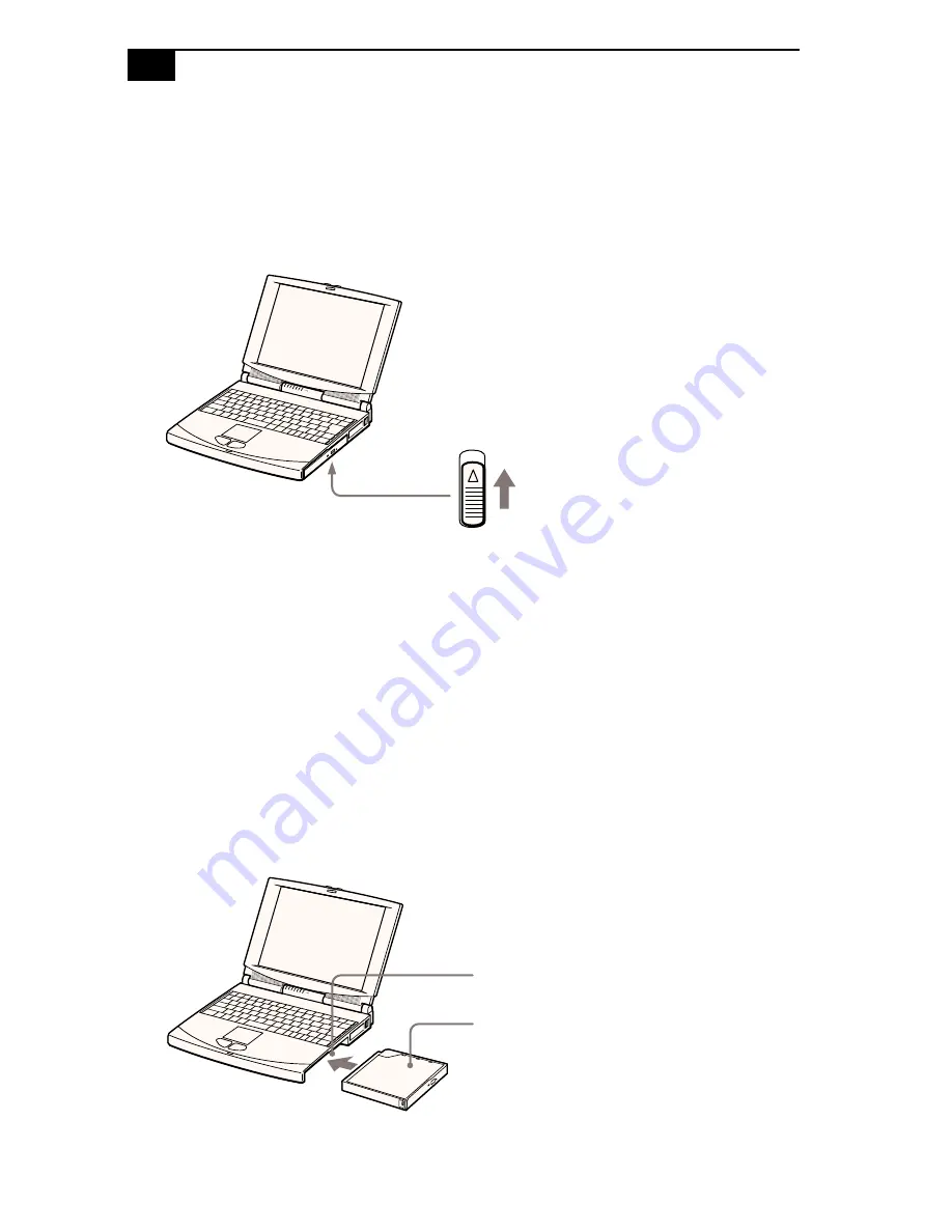
To remove the CD-ROM drive 

1

Turn off the computer before removing the CD-ROM drive.

2

There is an Eject lever on the bottom of the CD-ROM drive. Slide this 
lever in the direction of the arrow.

3

Slide the drive out of the multi-purpose bay. 

4

Insert the weight saver. See “Using the Weight Saver” on page 40.

To re-insert the CD-ROM drive

1

Turn off the computer.

2

If another device is in the multi-purpose bay, remove the device. See 
“To remove the floppy disk drive” on page 25 or “To remove the 
second battery pack” on page 39.

3

Insert the CD-ROM drive into the multi-purpose bay with the label 
side facing up.

Drive Eject lever on bottom

Multi-purpose bay

CD-ROM drive
(supplied)

Summary of Contents for Vaio PCG-745

Page 1: ...Sony Notebook Computer User Guide PCG 745 PCG 747 ...

Page 2: ...Partner Sony has determined that this product meets the ENERGY STAR guidelines for energy efficiency Energy Star is an U S registered mark Specifications are subject to change without notice Safety Information Owner s Record The model number and serial number are located on the bottom of your Sony Notebook Computer Record the serial number in the space provided here Refer to the model and serial n...

Page 3: ...thorized Sony technicians Improper repairs can create a safety hazard Do not handle damaged or leaking lithium ion batteries Danger of explosion if battery is incorrectly replaced Replace only with the same or equivalent type recommended by the manufacturer Discard used batteries according to the manufacturer s instructions The battery pack used in this device may present a fire or chemical burn h...

Page 4: ... Windows 98 14 Registering Your Computer 15 Using the Keyboard 16 Using the Touchpad 22 Using the Floppy Disk Drive 23 Using the CD ROM Drive 26 Using the Earphone with Remote Control 29 Using PC Cards 32 Using Infrared Communication Devices 34 Using Power Saving Modes 36 Using a Second Battery Pack 37 Using the Weight Saver 40 Connecting Peripheral Devices Connecting a PC card modem 42 Connecting...

Page 5: ...onnecting a Digital Video Camera Recorder 59 Connecting a Universal Serial Bus USB Device 60 Using the Media Bar 61 Media Bar Functions 62 Customizing Your Notebook Computer Displaying the Sony Notebook Setup Screen 63 Controlling Power Management 65 Displaying Battery Information 68 Selecting the Display Mode 71 Getting Help About Sony s Support Options 73 Troubleshooting 74 Using the Product Rec...

Page 6: ...ve Matrix LCD screen for the PCG 745 and enables you to take advantage of today s advanced multimedia applications games and entertainment software Multimedia features Enjoy the stereo speakers or use the supplied earphone to listen to audio and video CDs The earphone includes a remote control You can even listen to audio CDs when your computer is in suspend sleep mode Windows 98 Your system inclu...

Page 7: ...e complete list of the items that come with your computer in the About Your Sony Notebook Computer guide Main unit Floppy disk drive Phone cable Weight Saver AC adapter Power cord Rechargeable Earphone battery pack Video cable Floppy disk drive cable PC card modem User manuals Product Recovery Phone plug installed CD ROM drive CD ROM ...

Page 8: ...f the computer may strain muscles or tendons Furniture and posture Sit in a chair with good back support Adjust the level of the chair so your feet are flat on the floor A footrest may make you more comfortable Sit in a relaxed upright posture and avoid slouching forward or leaning far backward Viewing angle of the computer s display Use the display s tilting feature to find the best position You ...

Page 9: ... to your comfort and work effectiveness Tilt stand You use the tilt stand to place the computer at an angle that allows comfortable typing Placement of an external display When using an external display set the display at a comfortable viewing distance Make sure the display screen is at eye level or slightly lower when you are sitting in front of the monitor ...

Page 10: ...Locating the Controls and Connectors Front LCD screen pages 20 83 Power indicator pages 12 18 Speakers page 56 Hard disk drive indicator page 18 Keyboard page 16 Battery 1 2 indicators pages 18 68 Touchpad page 22 Num Lock indicator page 19 Left right button page 22 Caps Lock indicator page 19 Microphone page 57 Scroll Lock indicator page 19 1 2 Num Lock Caps Lock Scroll Lock 1 7 2 8 3 9 4 10 5 11...

Page 11: ...entilation slot located directly above the earphone connector Do not cover the ventilation slot when your computer is on All connectors for this notebook are SELV Safety Extra Low Voltage according to EN60950 Phone cable and phone cable connectors TNV Telecommunication Voltage according to EN 60950 AC adapter mains connector and power cord hazardous voltage according to EN 60950 1 4 2 5 3 6 ...

Page 12: ... bay page 23 DC In page 8 Monitor connector page 52 Serial COM1 connector page 58 Docking station page 44 Infrared port page 34 FDD Printer connector page 51 USB connector page 60 Video Out connector page 54 Mouse Keyboard connector page 56 2 1 1 2 cover cover 1 6 2 7 3 8 4 9 5 ...

Page 13: ...uter 2 Plug one end of the power cord into the AC adapter 3 Plug the other end of the power cord into an AC outlet Use your notebook only with the supplied AC adapter To disconnect your notebook completely from mains voltage unplug the AC adapter Please make sure that the socket outlet is easily accessible Notebook computer DC in AC adapter supplied Power cord supplied 1 2 3 SELV according to EN60...

Page 14: ...ate option The battery pack that comes with your computer is not fully charged at the time of purchase Follow the steps below to insert and charge the battery pack To insert the battery pack 1 Open the cover of the battery bay 2 Insert the battery pack into the battery bay on the left side of the computer 3 Close the cover of the battery bay To charge the battery pack 1 Connect the AC adapter to t...

Page 15: ...n on checking the battery life There are two battery indicator lights on the computer Battery Indicator Meaning 1 Indicates the status of the battery pack in the battery bay on the left side of the computer 2 Indicates the status of the battery pack in the multi purpose bay on the right side of the computer Battery Indicator Light Status Meaning On The computer is using battery power Flashing with...

Page 16: ...tomatically enters System Hibernation mode This may result in data loss as the system changes modes You can extend battery life by changing the power management modes in the PowerPanel utility See Using Power Saving Modes on page 36 The battery pack supplied with your computer is a lithium ion battery and can be recharged at any time Charging a partially discharged battery does not affect battery ...

Page 17: ...t of the computer until the power indicator light turns on green If you hold the power switch in the on position for more than four seconds the computer turns off Note on contrast PCG 745 only as the contrast of a LCD is variable adjust the contrast as follows To increase contrast press Fn F6 and then or To decrease contrast press Fn F6 and then or LCD lock lever Power switch Power indicator ...

Page 18: ... these steps to shut down your computer Respond to any prompts warning you to save documents If you are unable to shut down your computer using the steps described above press the Ctrl Alt Delete keys at the same time and select Shut Down in the Task manager window to restart the computer If you are unable to restart the computer in this way you can slide the power switch forward and hold for four...

Page 19: ...n overview of the process 1 Gathering information Enter your name Read and accept the License Agreement Enter your Certificate of Authenticity number located on the cover of the Introducing Windows 98 manual 2 Windows 98 setup Click the Finish button on the Windows 98 Setup Wizard screen 3 Selecting your computer settings If necessary change the Time Zone Date and Time on the Date Time Properties ...

Page 20: ... guarantee conditions Follow these steps to use the Sony Notebook Computer s online registration service 1 Enter the information requested on the online registration form 2 Click the Register now button and complete the form 3 Click the Send Directly Button to register your computer via modem to modem connection Your computer automatically transfers your registration information using your PC Card...

Page 21: ...culations such as addition and subtraction Note that you must press the Num Lock key to activate the numeric keypad When you do so the Num Lock light will be on Navigation keys Several keys are devoted to moving the cursor on the screen the four arrow keys which also function as the Home End Page Up and Page Down keys Correction keys The Insert Back Space and Delete keys enable you to make correct...

Page 22: ...another key the Ctrl Control and Alt Alternate keys offer another way to give commands For example in many applications instead of choosing the Save command from a menu you can hold down Ctrl and press S referred to as Ctrl S The Shift key is used to produce capital letters or special symbols such as and Windows 98 key The key with the Windows logo displays the Windows 98 Start menu it s the equiv...

Page 23: ... This is the equivalent of selecting Run from the Start menu Fn Pause Displays the Properties window This is the equivalent of double clicking the System icon in the Control Panel Indicators Functions Power Lights when the power to the computer is turned on Flashes in system suspend mode Turns off when the computer is in System Hibernation mode or powered off Hard disk Lights when data is being re...

Page 24: ...en the letters appear in uppercase as you type The Shift key lowers the case of typed letters when Caps Lock is on Turns off when letters appear in lower case as you type unless you hold down the Shift key Scroll Lock Turns on when the screen scrolls differently Exactly how it scrolls depends on the specific application It has no effect in many applications Turns off when information moves across ...

Page 25: ...e brightness of the LCD To increase light intensity press Fn F5 and then or To decrease light intensity press Fn F5 and then or Fn F6 Contrast control For PCG 745 Adjusts the contrast control on the LCD display To increase contrast press Fn F6 then or To decrease contrast press Fn F6 then or For PCG 747 The contrast control is not currently used on the LCD display Fn F7 Switch to the external disp...

Page 26: ...ned off To return the system to the original state use the power switch to turn on the power Fn E Eject CD ROM Ejects the CD ROM tray This command is active only when the CD ROM tray is in the multi purpose bay it is inactive when the drive is in the docking station Fn F Change the display size Zooms the display size in or out when the display is set to low resolution Fn D Video standby Turns off ...

Page 27: ...once In many applications this action displays a shortcut menu of context sensitive choices Drag Slide one finger while pressing the left button When your finger reaches a touchpad edge the pointer keeps moving until you lift your finger Use this action to select and move objects Scroll Move your finger along the right edge of the touchpad See Mouseware Properties for information on touchpad featu...

Page 28: ... ROM and the floppy disk drive at the same time use the floppy disk drive as an external drive If you connect the floppy disk drive externally while your computer is on use the Sony Notebook Setup utility to select Floppy Disk Drive See Displaying the Sony Notebook Setup Screen on page 63 for details To connect the floppy disk drive externally Connect the floppy disk drive to the FDD Printer conne...

Page 29: ...emove the second battery pack on page 39 3 Insert the floppy disk drive into the multi purpose bay with the VAIO label facing up Continue pushing the drive into the bay until the Eject lever locks into place To insert a diskette 1 Hold the diskette with the label side facing up 2 Gently push the diskette into the drive until it clicks into place Multi purpose bay Floppy disk drive Floppy disk driv...

Page 30: ...e is an Eject lever on the bottom of the floppy disk drive Slide this lever in the direction of the arrow 3 Slide the drive out of the multi purpose bay 4 Insert the weight saver See Using the Weight Saver on page 40 If you have difficulty removing a diskette from the floppy disk drive remove the floppy disk drive from the multi purpose bay Eject button LED indicator Drive Eject lever on bottom ...

Page 31: ...uter 2 Press the Eject button to open the CD ROM drive The CD tray slides out 3 Place the CD ROM disc in the tray with the label side facing up Push the disc onto the hub until the disc clicks into place When the computer is in System Suspend or System Hibernation mode you cannot insert a CD ROM disc See Controlling Power Management on page 65 for more information on System Suspend and System Hibe...

Page 32: ...he disk firmly When you finish using the CD ROM press the Eject button to remove the CD ROM disc When the computer is in system suspend or system hibernation mode you cannot remove a CD ROM disc See Controlling Power Management on page 65 for more information about system suspend and system hibernation modes If the CD ROM disc does not come out when you press the Eject button turn off the computer...

Page 33: ...f the multi purpose bay 4 Insert the weight saver See Using the Weight Saver on page 40 To re insert the CD ROM drive 1 Turn off the computer 2 If another device is in the multi purpose bay remove the device See To remove the floppy disk drive on page 25 or To remove the second battery pack on page 39 3 Insert the CD ROM drive into the multi purpose bay with the label side facing up Drive Eject le...

Page 34: ...ro plug of the earphone to the earphone remote control connector not to the Earphone connector of the computer 2 Connect the earphone remote control to the Earphone connector on the computer 3 While holding down the Fn key press Esc The computer enters system suspend mode 4 Press the Stop button on the remote control 5 Press the Eject button to open the CD ROM drive The CD Tray slides out 6 Place ...

Page 35: ...e only the supplied earphone remote control You cannot operate this feature with the remote control supplied with other models To remove an audio CD from the CD ROM drive remove the CD within one minute after pressing the Stop button on the remote control If the CD tray does not open press the Stop button and try again Your earphone with remote control may look different from the pictures illustra...

Page 36: ...When you are not using the earphone remote control slide Hold in the direction of the arrow To unlock slide Hold back To Press Find the beginning of the current track AMS side of once Find the beginning of previous tracks AMS side of repeatedly Find the beginning of the next track AMS side of once Find the beginning of succeeding tracks AMS side of repeatedly Go forward quickly Hold down side of G...

Page 37: ...he outside of the computer and push it in 2 Remove the PC card slot protector When you use a Type III PC card you need to remove both the top and bottom PC card slot protectors The PC card slots can accommodate at the same time two Type I two Type II or one Type III PC card These slots are compatible with Card Bus Both upper and lower slots are compatible with ZV Zoomed Video port To insert the su...

Page 38: ...rting a card check that you are inserting the card with the correct orientation see PC card label Some PC cards may require you to disable unused devices using Sony Notebook Setup See Displaying the Sony Notebook Setup Screen on page 63 Use the latest driver software provided by the PC card s manufacturer If you see the mark on the PC card in Device Manager tab of System Properties remove the driv...

Page 39: ...red ports on the computer and the digital camera so that they are in a direct line To use infrared communication with another computer Align the infrared ports on the two computers so that they are in a direct line When performing a data transfer with any software using infrared enable the IrDA in the Control panel of Windows as follows 1 In the Control panel choose Infrared then Options 2 Check E...

Page 40: ...o devices are too far apart or too close together data transfer may be interrupted or there may be noise in the transmission Do not cover the infrared ports with your hand or any other objects Avoid direct sunlight fluorescent light or flashing incandescent light close to the infrared ports See the manual that came with your digital still camera or other infrared communication device for more info...

Page 41: ...he LCD or the hard disk The power indicator light is on green in this mode System Suspend Mode The computer saves the current state of the system in RAM and switches off power to the CPU The power indicator light flashes amber in this mode To activate System Suspend Mode Press Fn Esc or slide the power switch forward quickly You can also use the PowerPanel utility to enter system suspend mode To r...

Page 42: ...d rechargeable battery pack With two battery packs you can extend the time that you use your computer with battery power When using two battery packs the battery pack you insert first charges first The battery pack you insert second charges when the first battery pack is 85 full You can determine which battery pack is charging by the battery indicator light status To insert a second battery pack 1...

Page 43: ...ttery 2 indicator light turns on 3 Attach the Weight Saver to the computer to stabilize the battery pack See also Using the Weight Saver on page 40 Battery indicator Battery pack Multi purpose bay Label side facing down Battery pack Weight saver ...

Page 44: ...d battery pack 1 There is an Eject lever on the bottom of the weight saver To remove the battery pack slide this lever in the direction of the arrow 2 Remove the weight saver and then pull out the battery pack 3 Re insert the weight saver See Using the Weight Saver on page 40 To determine the amount of time the battery lasts see Displaying Battery Information on page 68 1 2 Second battery pack not...

Page 45: ...See To remove the floppy disk drive on page 25 To remove the CD ROM drive on page 28 or To remove the second battery pack on page 39 2 Slide the weight saver in the direction of the arrow until it clicks To remove the Weight Saver There is an Eject lever on the bottom of the weight saver To remove the weight saver slide this lever in the direction of the arrow Weight saver supplied Weight saver Ej...

Page 46: ...xternal mouse or keyboard page 56 External speakers page 56 External microphone page 57 Digital still camera or other serial device page 58 Digital video camera recorder page 59 Universal serial bus USB device page 60 Before you connect peripherals turn off the computer and all peripherals Connect the power cord only after connecting all cables Turn on the computer only after turning on all periph...

Page 47: ... card modem supplied in the slot of the computer label facing up push it gently until the release button ejects completely Put back the release button 2 Plug the phone line jack into the left connector of the PC card 3 Plug the other end into the wall jack use the phone plug supplied Use the supplied communication tool which provides a full range of features fax data telephone directory See About ...

Page 48: ...hone Connecting to an ISDN line Your PC card modem is ready for connection to ISDN Digital Network offering transmission of voice data fax See your retailer for all information and accessories Models of GSM Card programming Sony CMD Z1 and Z1 Plus Ready Sony CM DX1000 Ready to be re programmed program supplied on your Hard Disk and Recovery CD ROM Other GSM phones See your retailer Phone cables an...

Page 49: ... technology Your operating system supports a limited number of USB devices You may need to install device drivers supplied with your USB device before using the USB device Network docking station only Video Out page 54 Line Out USB page 60 Monitor page 52 Mouse Keyboard page 56 Printer page 51 DC In page 8 Serial COM1 page 58 Joystick use only analog joysticks Network ethernet Microphone page 57 S...

Page 50: ...cover that protects the docking station port 3 Align the indentation on the bottom of the computer with the guide post on the docking station Use this docking station with the model running on Windows 98 When using the notebook computer with the docking station keep the AC adapter connected to the docking station To prevent the data being damaged and a malfunction occuring do not remove the AC ada...

Page 51: ...il it stops 5 Slide the docking station lever into the LOCK position to secure your computer in the docking station 6 Plug the cable attached to the AC adapter into the DC IN connector on the docking station Plug the power cord into the AC adapter and an AC outlet Use the AC adapter supplied with your docking station or the Sony optional PCGA AC7 AC71 adapter Guide posts Docking station port Docki...

Page 52: ... computer The IN USE indicator light turns on To charge a battery pack using the docking station 1 Open the cover of the battery charger bay 2 Insert the battery pack Battery charger Multi purpose bay bay Power Battery In use Docking station charger Label side facing Battery pack down ...

Page 53: ...place it on a slant while the battery is in the docking station charger bay To operate your computer using battery power you must insert the battery in the computer s battery bay The docking station bay is designed to charge batteries and cannot be used as a power source for your computer or docking station The battery inserted in the computer s battery bay has priority over the battery inserted i...

Page 54: ...Using the Weight Saver on page 40 Do not leave the multi purpose bay empty To remove your computer from the docking station when the power is on 1 Check that the charged battery is inserted in the computer 2 On the Start menu select Eject Alternatively press Fn F9 The IN USE indicator turns off If you press Fn F9 the computer beeps The battery charger indicator is a reference for the battery charg...

Page 55: ...Turn off your computer and the connected peripherals 2 Slide the docking lever forward into the RELEASE position to disengage the computer from the docking station 3 Lift the computer away from the docking station 4 Close the docking station port cover on the back of your computer You cannot remove your computer from the docking station when the power is on unless the charged battery is inserted i...

Page 56: ... Plug the printer cable supplied with the printer into this port on the computer See the manual that came with your printer for more information on installation and use Before using the printer you may need to change the FDD Printer setting in the Sony Notebook Setup software See Displaying the Sony Notebook Setup Screen on page 63 Printer Power cord Printer cable supplied with the printer to FDD ...

Page 57: ...nto the display and the other end into an AC outlet To connect a multimedia computer display You can connect the notebook computer to a multimedia computer display that includes built in speakers and a microphone 1 Use the symbol to locate the Monitor connector Plug the display cable into this connector 2 Use the symbol to locate the Earphone connector Plug the speaker cable into this connector Se...

Page 58: ...lay such as the Sony LCD Projector See the manual that came with your displays for more information on installation and use You may not be able to display the computer s LCD and external display according to the types of computer display and projector Multimedia computer display Power cord Display cable to Monitor to to Projector Power cord Audio cable not supplied RGB signal cable to Monitor to ...

Page 59: ...llowing keys to select a display See also Selecting the Display Mode on page 71 for more information See the manual that came with your TV for more information on installation and use To Press Result Switch to the VGA monitor Fn F7 Toggles between the LCD the external display connected to the Monitor connector and both the LCD and external display together Select LCD or TV Fn F8 Toggles between th...

Page 60: ...CD VGA to see the picture on both the LCD and the TV screen 4 If the picture on the TV screen is not the full one press Fn F7 again displays picture on TV only 5 Adjust the refresh rate With the PCG 745 resolution 800x600 1 Connect the cable between the PC or Docking Station and the Sony TV 2 Press Fn F7 LCD VGA to see the picture on both the LCD and the TV screen 3 If the picture on the TV screen...

Page 61: ...into this connector with the mark facing up Connecting External Speakers You can enhance the sound quality of your computer by connecting external speakers See the manual that came with your mouse or keyboard for more information on installation and use Before you connect or disconnect the mouse or keyboard turn off the computer After connection restart To use a mouse connected to the Serial port ...

Page 62: ...ound input by using an external microphone To connect an external microphone Use the to locate the Microphone connector Plug the microphone cable into this connector See the manual that came with your speakers and microphone for more information on installation and use Make sure your speakers and microphone are designed for computer use Speakers Speaker cable supplied with speakers to earphone Mic...

Page 63: ...COM1 connector Plug the connecting cable into this port on the computer and into the Digital I O connector on the digital still camera See the manual that came with your digital camera or other serial device for more information on installation and use If you use a digital camera that has an infrared data communication system or other infrared communication device see Using Infrared Communication ...

Page 64: ...order may need to be connected differently Connect only one of the i LINK connectors when connecting the digital video camera See the manual that came with your digital video camera recorder for more information on installation and use The i LINK connector on the docking station does not supply power to external devices generally powered by i LINK connectors The docking station supports a transfer...

Page 65: ...See the manual that came with your USB device for more information on installation and use When you make the PowerPanel timer setting that allows your computer to enter system suspend or system hibernation mode your computer may enter system suspend or system hibernation mode while you are using the USB device such as a USB mouse or USB keyboard Therefore when using USB devices select AC Profile o...

Page 66: ...ingle control bar across the top of the screen with buttons similar to the controls on a VCR or CD player remote control To expand the Media Bar You can expand the bar to double height to access more functions by clicking the Expand button at the far right To return to single height click the Restore button To change the Player bar to a floating window To change the bar into a floating window drag...

Page 67: ... Repeat all of the selections in order Repeat a single selection Play all of the selections in a random order Video images display in a separate Movie window which you can move and resize to full screen If the CD supports PlayBack Control for example Video CD ROM format you can select specific scenes or still images by their assigned numbers The Media Bar features extensive and detailed in online ...

Page 68: ...ettings You can also refer to the Sony Notebook Setup Help for more detailed information Displaying the Sony Notebook Setup Screen To display the Sony Notebook Setup screen 1 Click the Start button on the Windows 98 taskbar 2 In Programs select Sony Notebook Setup 3 Select the tab for the item you want to change See Notebook Setup Tabs on page 64 4 After you finish click OK ...

Page 69: ...rd drive inserted into the docking station as well as other drives inserted into your computer Touchpad When you connect an optional mouse to the Serial port of your computer you can make your touchpad inactive You can also customize the settings of your mouse using the mouse utility Power On Password Set the password to secure your computer Enable Ports Enabling or disabling ports releases resour...

Page 70: ...ofiles or you can create your own profile to suit your portable computing needs The predefined profiles are Other available profiles Configure PowerPanel with some other profiles right click on the Toolbar and choose Customize Icon Description Maximum Performance Provides the best system performance while still conserving power Maximum Battery Life Provides power saving features to give you maximu...

Page 71: ...s for LCD Video Standby Hard Disk Sleep and System Suspend to optimize power management for your system System Suspend Puts the system into System Suspend mode a power management state that saves the state of the system and peripheral devices in memory RAM Power consumption reduces to a minimum and the system remains on To return the system to the active state press any key or the power switch on ...

Page 72: ...for more information PC Card Controls the PC card sockets Click this button to open the PC Card PCMCIA Properties dialog box You can view the properties for the PC cards Speed Controller Controls the speed at which the CPU performs Click this button to open the Speed Controller dialog box When you select the Auto checkbox the CPU performs at full speed while the system is active and at 25 of full ...

Page 73: ...atteryScope 1 Click the Start button on the Windows 98 taskbar 2 In Programs click BatteryScope When you move the pointer over the battery icon on the taskbar a tooltip appears indicating the total capacity remaining in the battery and the estimated time until the battery fully discharges You can also view battery gauges on the shared PowerPanel and BatteryScope toolbar Percentage indicator Displa...

Page 74: ... detailed information about the batteries Click the battery icon on the application bar to display the BatteryScope window The screen appears displaying the General tab which contains information such as the estimated time to empty and charging time Battery icon Battery status Discharging Charging Not in use No battery ...

Page 75: ... to display information for the battery in the bay on the right side You can display the information about each battery such as estimated time to empty or product information To customize the BatteryScope application bar and alarm system You can customize the BatteryScope application bar to suit your portable computing needs as well as to modify the alarm settings Refer to the BatteryScope Help fo...

Page 76: ...s click Advanced button 5 Click the NeoMagic tab 6 Click Display Options 7 Select one of the options under Display Mode Display modes Functions Monitor Displays only an external display connected to the Monitor connector on your computer LCD Displays only the Liquid Crystal Display LCD on your computer Monitor LCD Simultaneously displays both an external display connected to the Monitor connector ...

Page 77: ...nector You can adjust the refresh rate when you select Monitor as the display mode If you want to display images on the TV that is connected to the Video Out connector do not connect any equipment to the Monitor connector TV Options Function Image Filter Adjusts the flicker Optimal TV Setting Adjusts the resolution for optimal TV viewing PAL SECAM Selects the PAL SECAM TV system NTSC Selects the N...

Page 78: ...so includes a packing list and technical specifications for your notebook computer It is included with your computer as an electronic document The Customer Service Guide gives you complete information on communicating with VAIO Link Response Centre Please also refer to this guide to get extended guarantee conditions The VAIO Channel offers on line information about your notebook computer and other...

Page 79: ...cables are connected firmly as described in Connecting Peripheral Devices on page 41 If you plugged the computer into a UPS make sure the UPS is turned on and working If you are using an external display check that it is plugged into a power source and turned on Check that the brightness and contrast controls are adjusted correctly See the manual that came with your display for details Moisture co...

Page 80: ...up or crashes Contact the software publisher or designated provider for technical support See the About Your Sony Notebook Computer guide for a list of phone numbers My mouse doesn t work If you are using an external mouse check that the mouse is plugged into the mouse connector See Connecting an External Mouse or Keyboard on page 56 for details My touchpad interprets a single tap as a double clic...

Page 81: ...that it is turned on Check that the power indicator on the front panel of the computer is on Check that the battery packs are inserted properly and that they are charged Adjust the brightness of the LCD page 18 The computer may be in LCD video standby mode Press any key to activate the display The video output may be directed to an external display Press Fn F7 until video output appears on the LCD...

Page 82: ...rogram s instructions Check the volume of your speakers Clean the CD ROM disc Moisture condensation may have occurred Leave the computer for at least 1 hour while the computer is turned on When I double click an application icon a message appears such as You must insert the application CD into your CD ROM drive and the software does not start Some titles require specific files that are located on ...

Page 83: ...k that the microphone is plugged into the Microphone connector See Connecting an External Microphone on page 57 for details When I press Fn F3 I see the message Muting Click the Volume icon in the Windows 98 taskbar When the Volume cursor appears disable Mute by clicking this option You can also disable Muting by pressing Fn F3 again About modem My modem PC card doesn t work Check that your PC car...

Page 84: ...om any line noise If your problem is fax related check that there are no problems with the fax machine you are calling and that it is compatible with fax modems If you are having a problem connecting with your Internet Service Provider check that the ISP is not experiencing technical problems If you have a second phone line available try connecting the modem to that line About peripherals My PC ca...

Page 85: ...overy will completely reinstall the originally configured system on your PC Applying a system recovery means that you will lose all your data stored on the hard drive Therefore before applying a system recovery save your data stored on the hard disk to an external disk If this is not possible under Windows 98 try to save your data from the DOS prompt to a floppy CAUTION ensure that your computer i...

Page 86: ...er does not start the system recovery utility Refer to your Customer Service Guide to call VAIO Link by phone or by fax Performing an Application Recovery The application recovery utility allows you to reinstall individual applica tions Reinstallation of a program can fix the problems encountered in a program that does not run correctly anymore Procedure for an application recovery 1 Turn on your ...

Page 87: ...roduct Recovery CD ROM Only device drivers that are not delivered with Win dows 98 can be found in the directory drivers in G Drivers Check all underlying sub directories for the appropriate driver Next launch the Add New Hardware wizard in the Windows start menu select settings then control panel to install the appropriate device ...

Page 88: ...images The screen becomes warm during operation This is normal and does not indicate a malfunction The LCD is manufactured using high precision technology You may however see tiny black points and or bright points red blue or green that continuously appears on the LCD This is a normal result of the manufacturing process and does not indicate a malfunction On the Power Source Your computer operates...

Page 89: ... On Installation Do not place your computer in a location subject to Heat sources such as radiators or air ducts Direct sunlight Excessive dust Moisture or rain Mechanical vibration or shock Strong magnets or speakers that are not magnetically shielded Ambient temperature of more than 35º C or less than 10º C High humidity To avoid interference do not place electronic equipment near your computer ...

Page 90: ... and other components Perform the procedures described in Adding Memory only at an ESD workstation If such a station is not available do not work in a carpeted area and do not handle materials that produce or hold static electricity cellophane wrappers for example Ground yourself by maintaining contact with an unpainted metal portion of the chassis while performing the procedure On Handling Disket...

Page 91: ...battery pack Do not expose the battery pack to any mechanical shock If you are not using the computer for an extended period of time remove the battery pack from the computer to prevent damage to the battery If after fully charging the battery pack the battery power is still low the battery pack may be reaching the end of its life and should be replaced You do not need to discharge the battery bef...

Page 92: ...uter Avoid rubbing the LCD screen as this can damage the screen Use a soft dry cloth to wipe the LCD screen Clean the computer with a soft cloth lightly moistened with a mild detergent solution Do not use any type of abrasive pad scouring powder or solvent such as alcohol or benzine ...

Page 93: ...s when you install memory modules in your computer See On Upgrading the System on page 85 Be careful when adding memory Mistakes when installing or removing a memory module may cause a malfunction Electrostatic discharge can damage electronic components Before touching a memory expansion board ensure the following You are discharged of static electricity by touching a grounded metal object You do ...

Page 94: ...n the bottom 4 Remove the memory module from its packaging 5 Install the memory module 6 Close the cover and tighten the screws 7 Turn on the computer 8 Click the My Computer icon with the right button and select Properties The System Properties screen appears 9 Click the Performance tab to view memory Slide the memory module into the slot The connectors snap into place when the board is correctly...

Page 95: ...disconnect all peripheral devices 2 Unplug your computer and remove the battery packs 3 Turn your computer upside down and open the cover on the bottom 4 Remove the memory module 5 Close the cover Pull the tabs in the direction of the arrows The memory module is released Pull the memory module in the direction of the arrow Performance tab 1 1 2 1 2 ...

Page 96: ...s 69 charging 9 39 indicator light status 10 indicator lights 5 10 18 37 inserting 9 inserting into battery bay 9 inserting into docking station 47 loading 9 power status 10 rechargeable 8 removing 11 37 39 BatteryScope utility 68 70 brightness adjusting 20 built in speakers 5 See also speakers 20 buttons Eject 26 27 Finish 14 left 5 Play 31 right 5 Start Windows 98 13 63 C cameras digital video r...

Page 97: ...4 52 mouse 44 multimedia computer display 52 network 32 44 phone line 42 power source 8 printer 51 projector 53 serial device 58 TV 54 USB device 60 weight saver 40 connectors DC In 7 8 44 eardphone 6 FDD Printer 7 23 51 i LINK 44 infrared 7 34 joystick 44 keyboard 5 7 44 Line In 6 44 Line Out 44 microphone 5 6 44 monitor 44 mouse 7 44 network 44 printer 51 SCSI 44 Serial port 7 44 USB 7 44 Video ...

Page 98: ...mouse 56 speakers 20 56 External Display connecting 52 F FDD Printer connector 7 23 44 51 Finish button 14 floppy disk drive bay 7 connecting 23 disconnecting 25 troubleshooting 77 Fn key 17 combination commands 20 function keys 17 G glare 3 GSM 43 guarantee 15 Guarantee card 15 H handling audio CDs 85 CD ROM discs 85 diskettes 85 Hard Disk Sleep power setting 66 hard drives 6 indicator light 5 18...

Page 99: ...isposal iv safety precautions iv loading battery pack 9 location for computer 3 M maintenance 84 87 Maximum Battery Life power setting 65 Maximum Performance power setting 65 Memory adding 88 memory module 88 89 installing 32 89 removing 90 microphone 6 connecting 57 connector 5 44 53 troubleshooting 78 Microphone connecting 57 modem troubleshooting 78 moisture condensation 85 monitor 7 44 71 conn...

Page 100: ...video standby 21 power setting AC Profile 65 LCD Video Standby 66 Maximum Battery Life 65 Maximum Performance 65 Power Management Off 65 System Hibernation 66 System Suspend 66 power sources 9 83 connecting 8 power standby Hard Disk Sleep 66 PowerPanel activating 67 customizing toolbar 65 66 67 precautions 84 pre installed software 73 Print Screen key 17 printer 7 44 connecting 51 connector 23 51 ...

Page 101: ...Setup screen 63 Sony Notebook Setup utility 23 speakers 5 built in 5 external 56 switching 20 troubleshooting 77 volume 20 Speakers connecting 56 Start button 13 63 starting computer 12 startup problems 13 Suspend Mode 36 switching display 20 monitor 20 System and Application Recovery CD 80 System Hibernation mode 66 system hibernation mode 21 36 System Recovery 80 System Suspend mode 66 system su...

Page 102: ...removing 40 Windows 98 Certificate of Authenticity 14 Control Panel 35 Explorer 18 Find window 18 Finish button 14 help 18 key 17 key combinations 18 License Agreement 14 registering 14 setup 14 Setup Wizard screen 14 Start button 13 taskbar 13 75 ...

Page 103: ...Sony Notebook Computer User Guide 98 Last revision 100898 ...

Reviews: