


1-3
12
Hookups and Settings
Hooking Up the Recorder
Follow steps 1 to 6 to hook up the recorder, and step 7 to make the initial settings for the recorder
(page 21).
Notes
• Plug cords securely to prevent unwanted noise.
• See the instructions supplied with the components to be connected.
• You cannot connect this recorder to a TV that does not have a SCART or video input jack.
• Be sure to disconnect the mains lead of each component before connecting.
Step 1: Unpacking
Check that you have the following items:
• Audio cord (pinplug
u
2
y
pinplug
u
2) (1)
• Video cord (pinplug
u
1
y
pinplug
u
1) (1)
• Aerial cable (1)
• Remote commander (remote) (1)
• R6 (size AA) batteries (2)
13
Ho
o
ku
p
s and
Se
tti
n
gs
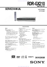
Step 2: Connecting the Aerial Cable
Connect the aerial cable by following the steps below. Do not connect the mains lead until you reach “Step
5: Connecting the Mains Lead” (page 18).
1
Disconnect the aerial cable from your TV and connect it to AERIAL IN on the rear panel of the
recorder.
2
Connect AERIAL OUT of the recorder to the aerial input of your TV, using the supplied aerial
cable.
AERIAL
IN
OUT
LINE 3 / DECODER
DIGITAL OUT
LINE 1 - TV
COAXIAL
PCM/DTS/
MPEG/
DOLBY DIGITAL
PCM/DTS/MPEG/
DOLBY DIGITAL
COMPONENT
VIDEO OUT
PB/CB
PR/CR
Y
LINE 2 OUT
L
AUDIO
VIDEO
R
LINE 4 IN
L
AUDIO
VIDEO
R
S VIDEO
LINE 2 OUT
DIGITAL OUT
VIDEO OUT
SELECT
RGB
COMPO-
NENT
OPTICAL
AERIAL
IN
OUT
DVD recorder
TV
to AERIAL OUT
to AERIAL IN
Aerial cable (supplied)
: Signal flow
14
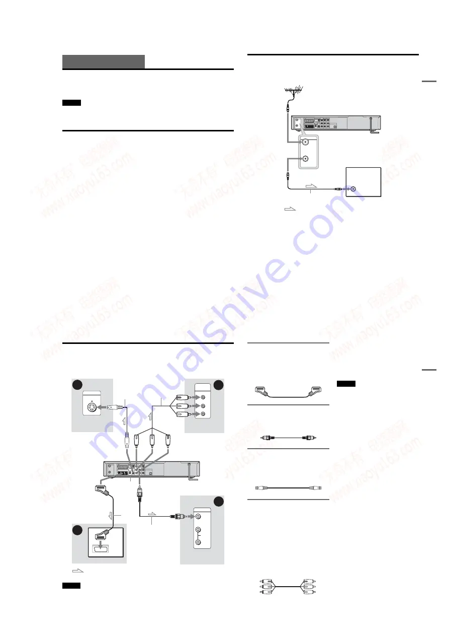
Step 3: Connecting the Video Cords
Select one of the following patterns
A
through
D
, according to the input jack on your TV monitor,
projector, or AV amplifier (receiver). This will enable you to view pictures. Audio connections are
explained in “Step 4: Connecting the Audio Cords” (page 16).
Note
Do not connect more than one type of video cord between the recorder and your TV at the same time.
INPUT
S VIDEO
P
R
P
B
Y
COMPONENT
VIDEO IN
VIDEO
AUDIO
INPUT
L
R
PCM/DTS/MPEG/
DOLBY DIGITAL
LINE 2 OUT
L
AUDIO
VIDEO
R
LINE 4 IN
L
AUDIO
VIDEO
R
DIGITAL OUT
OPTICAL
C
D
B
A
Video
cord (supplied)
Component video
cord (not supplied)
TV, projector, or AV
amplifier (receiver)
TV, projector, or AV
amplifier (receiver)
(green)
S-video cord
(not supplied)
TV, projector, or AV
amplifier (receiver)
(red)
(blue)
(green)
(blue)
(red)
: Signal flow
to COMPONENT
VIDEO OUT
to LINE 2 OUT (VIDEO)
DVD recorder
TV
SCART
cord (not
supplied)
15
H
ook
up
s and
Se
tti
n
gs
A
Connecting to a SCART input jack
Connect using a SCART cord (not supplied) to the
LINE 1-TV jack and your TV. Be sure to make the
connections firmly to avoid hum and noise.
See the operating instructions supplied with the
TV to be connected. Set the VIDEO OUT
SELECT switch on the rear panel to “RGB.”
B
Connecting to a video input jack
Connect using the video cord (supplied) to the
yellow LINE 2 OUT (VIDEO) jack. You will
enjoy standard quality images.
C
Connecting to an S VIDEO input
jack
Connect using an S-video cord (not supplied) to
the LINE 2 OUT (S VIDEO) jack. You will enjoy
high quality images.
D
Connecting to component video
input jacks (P
B
/C
B
, P
R
/C
R
,
Y)
Connect the COMPONENT VIDEO OUT jacks
using a component video cord (not supplied) or
three video cords (not supplied) of the same kind
and length. You will enjoy accurate colour
reproduction and high quality images.
Set the VIDEO OUT SELECT switch on the rear
panel to “COMPONENT.”
If your TV accepts progressive 625p format
signals, you must use this connection and set
[Progressive Mode] in [Settings] Setup to [On]
(see page 73). The PROGRESSIVE indicator
lights up on the recorder.
When playing “wide screen” images
Some recorded images may not fit your TV
screen. To change the aspect ratio, see page 72.
If you are connecting to a VCR
Connect your VCR to the LINE 3/DECODER
jack on the recorder (page 23).
Notes
• Consumers should note that not all high definition
television sets are fully compatible with this product
and may cause artifacts to be displayed in the picture.
In the case of 625 progressive scan picture problems, it
is recommended that the user switch the connection to
the ‘standard definition’ output. If there are questions
regarding our TV set compatibility with this model
625p DVD recorder, please contact our customer
service centre.
• When you connect the recorder to your TV via the
SCART jacks, the TV’s input source is set to the
recorder automatically when you turn the recorder on.
If necessary, press TV/DVD on the remote to return the
input to the TV.
Green
Red
Blue
Green
Red
Blue
www. xiaoyu163. com
QQ 376315150
9
9
2
8
9
4
2
9
8
TEL 13942296513
9
9
2
8
9
4
2
9
8
0
5
1
5
1
3
6
7
3
Q
Q
TEL 13942296513 QQ 376315150 892498299
TEL 13942296513 QQ 376315150 892498299


