2-2
PCWA-A100/C100 (UC)
Confidential
2-1-2. Inspecting the Access Point and PC Card
Inspecting the Access Point
Refer to “Inspection Setup Diagram” of Section 2-6, “How to Return to the Factory Settings”.
(Be sure to perform the inspection using the factory settings.)
Completely insert the DC plug of the AC adapter into the DC jack of the Access Point to be analyzed.
Insert the connector of the opposite end of the Ethernet cross cable connected to the desktop PC into the Ethernet terminal of the Access Point
until a click is heard.
Confirm that the POWER LED of the Access Point lights in green.
Insert the standard PC Card for inspection into the notebook PC.
Inspecting the PC Card
Refer to “Inspection Setup Diagram” of Section 2-6, “How to Return to the Factory Settings”.
Completely insert the DC plug of the AC adapter into the DC jack of the standard Access Point for inspection.
Insert the connector of the opposite end of the Ethernet cross cable connected to the desktop PC into the Ethernet terminal of the Access Point
until a click is heard.
Confirm that the POWER LED of the Access Point lights in green.
Insert the PC Card to be analyzed into the notebook PC.
2-1-3. Wireless LAN Link Test
A:
When Windows 95 version 4.00.950 is selected as OS of the notebook PC in “2-1-1 Preparation for Inspection - B”.
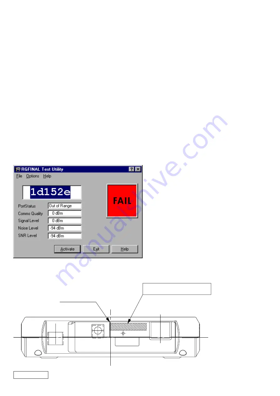
Notebook PC: Confirm that “FAIL” is displayed.
Enter the six-digit ID of the Access Point in the largest field and press the [Return] key.
ID Label Location
Line for ID Label
ID: 123456
Sn: 00UT12345678
Pn: 012756
ID Label


