background image

2-14

PCWA-A100/C100 (UC)

Confidential

48

Verifying communication with the
Access Point

Follow the steps below to verify that if the Wireless
LAN PC Card has a connection with the Access Point.

1

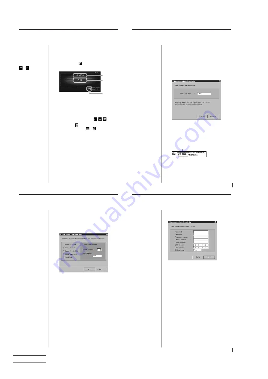
Double-click the 

 on the task tray.

The Wireless Pallete status window appears.

2

Verify the Nickname.

The Nickname identifies the Access Point with
which the computer has a connection. Verify that
the Nickname you entered (page 45) is displayed.

3

Verify the reception level.

The reception level indicator (

/

/

) indicates

the condition of the communications with the
Access Point. 

 indicates the optimum

communication. When 

 or 

 is displayed, no

communications are taking place between the
Access Point and the computer. Check the Access
Point configuration. For more information, refer
the Wireless Palette Help.

4

Verify the Computer Name.

The Computer Name is the computer name you
have specified on page 24 (Windows 98 Second
Edition) or page 34 (Windows 2000). The wireless
LAN connection is established with the computers
displayed.

Computer

Name
Nickname

Reception
Level/
Indicator

z

 Tips

The icon may appear as

 or 

 .

If so, no communications
are taking place with the
Access Point. Check the
Access Point's
configuration. For further
information, refer to the
Wireless Palette Help
files.

49

Setting up the Access Point

You can change the Access Point settings by using the
Basic Setup Utility. Changes to the settings may be
made by using the Custom Setup Utility as well.

This operation must be performed on a single
computer on the wireless LAN.

1

From the Start menu, click VAIO - Wireless LAN -
Basic Access Point Setup Utility.

The Basic Setup Utility starts.

2

Confirm that the Access Point ID displayed is the
one assigned to the Access Point you are
configuring, then click SCAN.
The Access Point ID is a six-digit number on the
label attached on the bottom surface of the Access
Point. If the Access Point ID displayed is different
from the one on the label, enter the correct ID.

Note

If an error message
appears, click OK then
confirm the following and
repeat step 2.
• The Access Point is

powered.

• The correct Access

Point ID is displayed.

• The Access Point and

the computer are
located within a rage of
approximately 50 m
(165 feet).

z

 Tip

To launch the Custom
Setup Utility, click the
Start button and select
VAIO - Wireless LAN -
Custom Access Point
Setup Utility.

Access Point ID

Factory-set Encryption KEY

50

3

Enter the common parameters,  Channel Number
and Encryption Key.

Select the channel that the Access Point uses for
wireless communications for Channel Number.
You can use Channel 1, 4, 7, or 10.

Enter any five-digit alphanumeric characters for
Encryption Key.

4

Select the access method to the Internet from
Connection Mode and click NEXT.

Select a destination to connect the Access Point.
Available options are Phone Connection, Cable
Modem/xDSL, ISDN Router/LAN, and Local
Only. The dialog that appears next depends on
your selection.

Note

Using the Wireless
Palette, enter the same
Encryption Key on every
computer in the wireless
LAN, as specified for the
Access Point.

z

 Tips

• If there are two or more

Access Points in close
proximity, assign a
unique channel number
to avoid radio
interference.

• The factory-set

Encryption Key of the
access point is the last
five digits of the Access
Point ID.

Note

If you have accidentally
selected a wrong access
method, click BACK and
select the correct one.

Note

If you are using the Access Point and are connecting within
an existing LAN that already has a DHCP server, do not use
the Phone Connection or Local Only connection modes.
Select Cable Modem/xDSL or ISDN Router/LAN connection
modes.
When the Wireless LAN Access Point is using Phone
Connection and/or Local Only connection modes, the Access
Point acts as a DHCP server.
An Access Point that is connected to a LAN that has another
DHCP server may experience the following problem while
using the Phone Connection or Local Only connection mode.
A client computer within the LAN may acquire an invalid IP
address from the Access Point, not from the regular DHCP
server.  If this happens, the client computer may not be able
to access the network because the IP address supplied by the
Access Point is a private IP address (10.0.1.2 - 17, by default).
Contact your network administrator before connecting a
Wireless LAN Access Point to an existing LAN.

51

Phone Connection:

The Enter Phone Connection Parameters dialog box
appears.

1

Enter data for Account ID, Password, Password
(re-enter), Phone Number 1, Phone Number 2, and
Dialing Mode and click NEXT.

The confirmation dialog appears.

2

Make sure you have made correct settings, then
click NEXT.

Changes to the Access Point settings are reflected
and the Finish screen appears.

3

Click LINK TEST.

The link test between the Access Point and the
computer is performed.

When the confirmation dialog box appears, click
FINISH to exit.

Note

If you must press “0” on
your telephone to hear
the tone signal and place
an outgoing call, you can
not use your telephone
line for Internet access
using the Access Point.
If you hear the tone signal
when you pick up the
receiver even though you
must press “0” to place an
outgoing call, you can use
your telephone line for
Internet access using the
Access Point. In these
situations, enter “0”
before the telephone
number for Phone
Number 1 and Phone
Number 2.

z

 Tips

• Phone Number 2 is the

alternate telephone
number to use when a
call to Phone Number 1
is not completed.

• Your Internet Service

Provider may specify
the DNS server(s). In
this case, enter data for
DNS Server 1 (DNS
Server 2).

Note

The indicators on the
Access Point flashes while
changes to the settings are
processed.
The link test is disabled
until the Access Point
POWER indicator turns
green.
(It takes approximately 30
seconds before the
POWER indicator turns
green.)

Summary of Contents for PCWA-C100

Page 1: ... Approx 5 W Dimensions With stand Approx 156 134 5 53 mm approx 6 1 4 5 3 8 2 1 8 inches w h d Without stand Approx 156 125 35 mm approx 6 1 4 5 1 7 16 inches w h d Mass Approx 480 g approx 17oz excluding the unit stand and the AC power adapter Operating temperature 5 C to 35 C 41 F to 95 F not condensed Environment temperature 20 C to 60 C 4 F to 140 F not condensed Supplied accessories Protocol ...

Page 2: ...oard In addition internal wiring has been routed and clamped so as to keep it away from hot or high voltage parts When mounting parts or routing wires therefore be sure to duplicate the original layout 4 Inspect after completing service After servicing inspect to make sure that all screws components and wiring have been returned to their original condition Also check the area around the repair loc...

Page 3: ...uired Tools 2 7 2 2 2 Network Setting of Desktop PC 2 7 2 2 3 Setting the Magic DHCP Server 2 8 2 3 Setup of Notebook PC 2 8 2 3 1 Required Tools 2 8 2 3 2 Network Setting of Notebook PC 2 8 2 4 Inspection Procedure of Access Point Modem 2 9 2 4 1 Preparation 2 9 2 4 2 Inspection 2 9 Extracted from the PCWA C100 Instruction Manual 2 10 2 5 Checking Symptoms Pointed Out by User Final Check 2 16 2 6...

Page 4: ...phone cable 7 DC IN 9V jack page 17 Used to connect the AC power adapter 8 ID label page 18 The Access Point ID and other information are printed on this label 9 10BASE T connector RJ 45 page 14 Used to connect to a cable modem xDSL modem ISDN router or hub Parts and indicators 8 LINE PHONE DC IN 5V 10BASE T 1 2 3 4 5 6 7 9 11 1 DATA indicator Lights up while data exchange is in progress 2 LINK in...

Page 5: ...C is not Windows 95 version 4 00 950 2 1 Procedure of Service Inspection of Access Point and PC Card 2 1 1 Preparation for Inspection A Complete the setup in advance Refer to Section 2 2 Setup of Desktop PC Start up Amea exe of the desktop PC B Complete the setup in advance Refer to Section 2 3 Setup of Notebook PC Start up RGFinal1 exe of the notebook PC If the OS of the notebook PC is not Window...

Page 6: ...nspecting the PC Card Refer to Inspection Setup Diagram of Section 2 6 How to Return to the Factory Settings Completely insert the DC plug of the AC adapter into the DC jack of the standard Access Point for inspection Insert the connector of the opposite end of the Ethernet cross cable connected to the desktop PC into the Ethernet terminal of theAccess Point until a click is heard Confirm that the...

Page 7: ... 1 Complete 2 1 2 Inspecting the Access Point and PC Card 2 Follow the procedure on pages 44 to 46 of the PCWA C100 Instruction Manual to establish the communication with the standard Access Point for inspection or the Access Point to be analyzed 3 Follow the procedure on page 48 of the PCWA C100 Instruction Manual to establish the communication with the standard Access Point for inspection or the...

Page 8: ...k Test Desktop PC Select Select Another Device from Analyze of the Amea exe menu of the desktop PC Click the Scan button Select the searched access point and click the OK button Confirm that the Remote IP Address is already entered and click the OK button ...

Page 9: ...CWA A100 C100 UC Confidential After Device located is displayed click the OK button Select Wireless Link Test from Analyze of the Amea exe menu Select the searched station name and click the Link Test button ...

Page 10: ...Poor No Connection is displayed do the procedure again from the beginning of Section 2 1 4 Ethernet Link Test If a message other than Good is displayed even when the test is executed again do the following When inspecting the Access Point Judge the Access Point as defective When inspecting the PC Card Judge the PC Card as defective ...

Page 11: ...quired software in advance Execute setup exe of magkdhcp zip after unzipping Place amea exe with mfc42 dll in an appropriate directory 2 2 2 Network Setting of Desktop PC Right click the Network Neighborhood icon on the desktop and select Properties Enter the IP address 192 168 0 254 confirm that the Specify an IP address option button is clicked in the IP Address text box of the IP Address tab En...

Page 12: ... 2 To install the server as a service run DHCP install This will install the server as a service and start it Default Renewing Time 1 min Default Expiry Time 1 min 3 To remove the server from the list of services run DHCP remove 2 3 Setup of Notebook PC 2 3 1 Required Tools Notebook PC that has a PCMCIA slot and PC Card card Driver for PC Card Mini600 exe RGFINAL program RGFinal1 exe The OS must b...

Page 13: ...uction Manual and install the software Installing software From P 40 4 Do the procedure on pages 44 to 46 and 48 of the PCWA C100 Instruction Manual and set the connection environment To establish communications with the Access Point From P 44 Verifying communication with the Access Point P 48 2 4 2 Inspection 1 Connect the phone line to the Access Point 2 Connect the AC power adapter to the Acces...

Page 14: ...r restarts verify that the Wireless LAN PC Card is working properly 1 From the Start menu click Settings then Control Panel The Control Panel window appears 2 Double click the System icon The System Properties dialog box appears 3 Click the Device Manager tab and check View devices by type Note Restarting the computer takes longer than booting 15 Note If a message This device is working properly i...

Page 15: ...100 Wireless PC Card is not displayed in step 3 above follow the steps below 1 Click Add on the Configuration tab The Select Network Component Type dialog box appears 20 2 Click Protocol then click Add The Select Network Protocol dialog box appears 3 Select Microsoft in the Manufacturers window and select TCP IP in the Network Protocols window 4 Click OK TCP IP Sony PCWA C100 Wireless PC Card appe...

Page 16: ...ion Information tab on the Network dialog box and specify the Computer name and Workgroup 2 Click OK The System Settings Change dialog box appears 3 Click Yes to restart the computer Proceed to the next section To set up sharing on the computer on page 25 on completion of these instructions Notes Assign a unique name of up to 15 alphanumeric characters to every computer connected to the same LAN T...

Page 17: ... Card to the computer 1 Double click the on the task tray The Wireless Palette status window appears Setting up the connection environment Wireless LAN connection z Tip If the icon is not on the tray select VAIO Wireless LAN Wireless Palette from the Start menu Access Point ID Factory set Encryption KEY 45 2 Click the Tool Box button The Tool Box window appears 3 Click Add The Add New Access Point...

Page 18: ...ns are Phone Connection Cable Modem xDSL ISDN Router LAN and Local Only The dialog that appears next depends on your selection Note Using the Wireless Palette enter the same Encryption Key on every computer in the wireless LAN as specified for the Access Point z Tips If there are two or more Access Points in close proximity assign a unique channel number to avoid radio interference The factory set...

Page 19: ...Connection 1 Double click the on the task tray 2 Click Connect Connection to the Internet service provider is established 3 Launch your web browser A home page is displayed 4 Click Disconnect The dial up connection is disconnected z Tip The icon may appear as or Notes The Access Point is configured with the manual connection mode at the time of shipment Clicking Connect initiates the dial up conne...

Page 20: ... PCWA C100 Instruction Manual to install the upgrade utility of the access point in the desktop PC Select Custom Setup in item 7 of Installing software and select only Access Point Firmware Upgrade Utility of Select Component to install the software Inspection Setup Diagram DHCP server software magkdhcp zip Inspection software amea exe mfc42 dll Desktop PC or notebook PC Ethernet must be set Ether...

Page 21: ...t switch Use only enough pressure to activate the switch 2 6 3 Running the Upgrade Utility Run the Upgrade Utility by clicking on Start VAIO Wireless LAN Access Point Firmware Upgrade The following figure will appear when the Firmware Upgrade Utility starts Enter the Access Point ID six digits of the Access Point of the firmware you want to upgrade and click UPGRADE The ID you need to use is locat...

Page 22: ...reset state with the Access Point ID you specified is found the following message is displayed Click OK Enter the IP address that you want to temporarily assign to the Access Point s Ethernet interface To connect to the same network as that of the same IP address assigned to the VAIO PC enter 192 168 0 253 and click OK The specified IP address is assigned to the Access Point s Ethernet interface t...

Page 23: ...fety Replace only with part number specified Les composants identifiés par une marque sont critiques pour la sécurité Ne les remplacer que par une pièce portant le numéro spécifié S P Ref No Part No Description 0S 1 1 468 527 11 ADAPTOR AC PCWA A100 S 2 1 779 696 11 ADAPTOR PLUG PCWA A100 S 3 1 783 801 21 CORD CONNECTION PCWA A100 S 4 X 4622 753 1 STAND ASSY PCWA A100 S 4 647 079 11 MANUAL INSTRUC...

Page 24: ...59 11 PCWA A100 C100 UC English 2000G1600 1 2000 Sony Corporation Published by PNC Planning Control Dept This manual and the constituent data may not be replicated copied nor reprinted in whole or in part without prior written authorization of Sony Corporation ...

Reviews: