background image

101

Adjustments and Settings from Menus

  Chap

te

r 5

   Men

u

 Dis

p

la

ys 
a

nd Det

a

iled

 S

e

ttin

gs

5-3-10 Using UMID Data

To perform operations from interviewing to editing 
effectively and to detect audio-visual materials easily 
when reusing them, metadata that provides additional 
information is recorded along with audio-visual data on a 
tape. As one of application of metadata, the UMID 
(Unique Material Identifier) is internationally 
standardized.

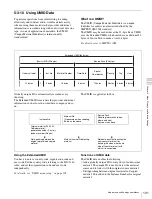
What is a UMID?

The UMID (Unique Material Identifier) is a unique 
identifier for audio-visual material defined by the 
SMPTE330M-2003 standard.
The UMID may be used either as the 32-byte Basic UMID 
or as the Extended UMID, which includes an additional 32 
bytes of Source Pack to make a total 64 bytes.

For details, refer to SMPTE 330M.

Globally unique ID is automatically recorded every 
shooting.
The Extended UMID is metadata that provides additional 
information such as location, time/date, company and so 
on.

The UMID is applied as follows:

Using the Extended UMID

You have to enter a country code, organization code and 
user code. Set the country code referring to the ISO-3166 
table, and set the organization code and user code 
independently.

For details, see “UMID menu setup” on page 102.

Functions of UMID data

The UMID data enables the following:
• Add a globally unique ID to every shot of audio-visual 

material. The unique ID is used to detect the material 
source and to link it with the original source material.

• Distinguishing between original material and copied 

material. 00 is added to the Instance Number for original 
material.

Extended UMID (64 bytes)

Basic UMID (32 bytes)

Source Pack (32 bytes)

Universal label

L

Inst. No.

Material Number

Time/Date

Spatial 

Co-ordinates

Country

Org

User

12 bytes

1

3 bytes

16 bytes

8 bytes

12 bytes

4 bytes

4 bytes

4 bytes

Instance No.

Material No.
ID generated when shooting
Same as the above

Source Pack
Shooting information (when, 
where and who)
Same as the above

Original material: 00 00 00
Copied material: 
generation number (1 byte) + 
random number (2 bytes)

M

Distinguishing between the 
original material and copied 
material

M

Material source ID/detecting 
material

M

Metadata pack that identifies the 
source of material unit by 
defining the when, where and 
who of the material unit with 
which it is associated.

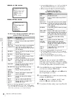
Summary of Contents for MSV-970

Page 1: ...ish 1st Edition Revised 2 The supplied CD ROM includes operation manuals for the MSW 970 970P Digital Camcorder English Japanese French German Italian Spanish and Chinese versions in PDF format For more details see 1 4 Using the CD ROM Manual on page 15 ...

Page 2: ...urning your used rechargeable batteries to the collection and recycling location nearest you For more information regarding recycling of rechargeable batteries call toll free 1 800 822 8837 or visit http www rbrc org Caution Do not handle damaged or leaking lithium ion batteries For the State of California USA only Perchlorate Material special handling may apply See www dtsc ca gov hazardouswaste ...

Page 3: ...e utilisé dans les environnements électromagnétiques suivants E1 résidentiel E2 commercial et industrie légère E3 urbain extérieur et E4 environnement EMC contrôlé ex studio de télévision Um die Gefahr von Bränden oder elektrischen Schlägen zu verringern darf dieses Gerät nicht Regen oder Feuchtigkeit ausgesetzt werden Um einen elektrischen Schlag zu vermeiden darf das Gehäuse nicht geöffnet werde...

Page 4: ...descargas eléctricas no abra el aparato Solicite asistencia técnica únicamente a personal especializado Para clientes de los EE UU y CANADÁ RECYCLADO DE BATERIAS DE IONES DE LITIO Las baterías de iones de litio son reciclables Useted podrá ayudar a conservar el medio ambiente devolviendo las baterías usadas al punto de reciclaje mas cercano Para más información sobre el reciclado de baterías llame...

Page 5: ...5 ...

Page 6: ...nctions 21 2 5 Menu Operating Section 26 2 6 Time Code System 28 2 7 Warnings and Indications 30 2 8 Warnings and Indications on the Display Panel 31 2 9 Indicators in the Viewfinder 33 Chapter 3 Recording and Playback 3 1 About Cassette 34 3 1 1 Loading and Unloading a Cassette 34 3 1 2 Preventing Accidental Erasure 35 3 2 Recording 36 3 2 1 Basic Procedures 36 3 2 2 Continuous Recording 37 3 2 3...

Page 7: ... for Recording 4 1 Adjusting the Black Balance and the White Balance 60 4 1 1 Adjusting the Black Balance 60 4 1 2 Adjusting the White Balance 61 4 2 Setting the Electronic Shutter 63 4 2 1 Shutter Modes 63 4 2 2 Selecting the Shutter Mode and Shutter Speed 64 4 3 Changing the Reference Value for Automatic Iris Ad justment 67 4 4 Adjusting the Audio Level 69 4 4 1 Manually Adjusting the Audio Inpu...

Page 8: ...ignals 93 5 3 3 Setting the Color Temperature Manually 93 5 3 4 Specifying an Offset for the Auto White Balance Setting 94 5 3 5 Assigning Functions to Assignable Switches 95 5 3 6 Setting the Date Time of the Internal Clock 97 5 3 7 Selecting the Lens File 98 5 3 8 Selecting the Aspect Ratio 98 5 3 9 Setting the CCD Scan Mode 99 5 3 10 Using UMID Data 101 5 4 Resetting USER Menu Settings to the S...

Page 9: ...System 120 7 5 1 Using the Supplied Microphone 120 7 5 2 Using an External Microphone 121 7 5 3 Attaching a UHF Portable Tuner for a UHF Wireless Microphone System 122 7 5 4 Connecting Line Input Audio Equipment 124 7 6 Tripod Mounting 124 7 7 Attaching Detaching the Shoulder Strap 125 7 8 Adjusting the Shoulder Pad Position 126 7 9 Putting on the Rain Cover Not Supplied 126 7 10 Connecting the Re...

Page 10: ...nts Video Camera Section 136 VTR Section 137 Recommended Additional Equipment 137 Menu List 139 OPERATION Menu 139 PAINT Menu 146 MAINTENANCE Menu 151 FILE Menu 159 DIAGNOSIS Menu 162 About a Memory Stick 163 Index 165 ...

Page 11: ...4 fps2 progressive scan video can be recorded subjected to pull down 24P mode providing imaging quality close to that of film MSW 970 only 1 More precisely 29 97 fps 2 More precisely 23 98 fps Camera signal processing for high quality video The 14 bit A D converter provides stable high quality images and reliability The high performance electronic shutter allows you to select extended clear scan m...

Page 12: ... inevitable in broadcasting LTC1 and VITC2 recording and LTC playback can be performed The built in time code generator can be synchronized with an external generator A lithium battery is the back up power supply for the built in time code generator enabling the time code to be held for approximately 5 years without being charged with the camcorder power supply The time code can be displayed in th...

Page 13: ... to expand the functions MSDW 903 Picture Cache Board Installing the board allows the camcorder to record up to several seconds of the picture before the REC button is pressed Picture Cache Function and to shoot pictures at intervals Interval Rec MSDW 904 Analog Composite Input Board Installing the board allows the camcorder to record an analog composite signal from external equipment connected to...

Page 14: ...g Composite Input Board MSDW 904 Viewfinder related equipment Name Purpose Magnification Part No Fog proof filter 1 547 341 11 Lens assembly 2 8 D to 2 0 D A 8262 537 A Lens assembly 3 6 D to 0 8 D A 8262 538 A Lens assembly 3 6 D to 0 4 D A 8267 737 A Lens assembly 3 magnification 2 4 D to 0 5 D A 8314 798 A BKW 401 Viewfinder Rotation Bracket AC power supply Battery Product Model name AC Adaptor...

Page 15: ...ture white flecks may appear on the screen 1 4 Using the CD ROM Manual The supplied CD ROM includes versions of the Operation Manual for the MSW 970 970P in English Japanese French German Italian Spanish and Chinese in PDF format 1 4 1 Preparations The following program must be installed on your computer in order to read the operation manuals contained on the CD ROM Adobe Reader Version 6 0 or hig...

Page 16: ... the adaptor To use an external battery connect its DC output cable to the DC IN connector c POWER switch This switch turns the main power supply on and off d LIGHT switch This determines how a video light connected to the LIGHT connector is turned on and off AUTO When the switch on the video light is in the on position putting the camcorder in recording mode turns the video light on automatically...

Page 17: ...the lens mount ring with this lever to lock the lens in position f Lens mount cap Remove this cap by pushing up the lens locking lever When no lens is mounted keep this cap fitted for protection from dust g LENS connector 12 pin Fit the lens cable to this connector Contact your Sony representative for more information about the lens you can use h Tripod mount When using the camcorder on a tripod a...

Page 18: ...n hear the alarm sound through the earphone 1 E E Abbreviation of Electric to Electric In E E mode video and audio signals input to the camcorder are output after passing through internal electric circuits only This can be used to check input signals e MONITOR switch and CH 1 2 CH 3 4 switch These switches together determine the channel selection for audio monitor output MONITOR switch and CH 1 2 ...

Page 19: ...ions 2 i LEVEL CH 1 CH 2 audio channel 1 and channel 2 recording level controls These controls adjust the audio levels of channels 1 and 2 when the AUDIO SELECT switches are set to MANUAL j AUDIO SELECT CH 1 CH 2 audio channel 1 and channel 2 adjustment method selection switches These switches select the audio level adjustment method for each of audio channels 1 and 2 AUTO Select this setting for ...

Page 20: ...s a WRR 855A 855B UHF Synthesized Tuner Unit not supplied l AUDIO OUT audio output connector XLR type 5 pin male This connector outputs the audio signals recorded on audio channels 1 and 2 or audio channels 3 and 4 The MONITOR CH 1 2 CH 3 4 switches allow you to select the audio signal to be monitored m AUDIO IN CH1 CH2 audio channel 1 and channel 2 input connectors XLR type 3 pin female and LINE ...

Page 21: ...e zebra pattern is displayed and stays OFF No zebra pattern is displayed MOMENT The zebra pattern is displayed and stays for 5 to 6 seconds The zebra pattern is factory set to indicate picture areas where the video level is approximately 70 You can use the setup menu to change the setting so that areas where the video level is 100 and above are also displayed at the same time 1 The zebra pattern a...

Page 22: ...from the viewfinder This indicator flashes when the battery level is running low or the disc is almost full l Viewfinder stopper Pull up this stopper to detach the viewfinder from the camera m LOCK knob To adjust the viewfinder position in the front rear direction loosen this knob and the viewfinder front rear positioning lever After adjustment retighten this knob and the viewfinder front rear pos...

Page 23: ...CAM Outputs the video signal from the camera When this is selected you can switch DCC1 on and off with this selector 1 DCC Dynamic Contrast Control Against a very bright background with the iris opening adjusted to the subject objects in the background will be lost in the glare The DCC function will suppress the high intensity and restore much of the lost detail and is particularly effective in th...

Page 24: ...or you can monitor the picture being shot by the camera or the picture played back by the VTR To choose between the composite video signal output and SDI signal output use the menu When synchronizing the time code of an external VTR with that of the camcorder connect this connector to the GENLOCK IN connector of the external VTR By installing the CBK SD01 extension board not supplied you can outpu...

Page 25: ... In such a case the VTR SAVE indicator in the viewfinder lights This function is effective when a setting other than OFF is selected for the STBY OFF TIMER item on the VTR MODE page of the MAINTENANCE menu The STBY OFF TIMER item also allows you to select the length of time until the camcorder turns to power saving mode For detailed information see 3 7 Setting the Stand by off Timer During Rec Pau...

Page 26: ...by pressing and turning this knob Turn Turn this knob to change the page or change item settings c STATUS ON SEL OFF menu display on page selection display off switch To enable this switch set the MENU ON OFF switch to OFF Closing the cover automatically sets the MENU ON OFF switch to OFF ON SEL Each time this switch is pushed upward a window to confirm the menu settings and status of the camcorde...

Page 27: ...EL PRST preset ESCAPE switch To enable this switch set the MENU ON OFF switch to ON Closing the cover automatically sets the MENU ON OFF switch to OFF CANCEL PRST Pushing this switch up to this position displays the message to confirm whether the previous settings are cancelled or settings are reset to their initial values depending on the menu operating condition Pushing this switch up to this po...

Page 28: ... RET button down with RETURN VIDEO set to ON on the GENLOCK page of the OPERATION menu This connector also accepts an external analog composite video signal When the MSDW 904 extension board optional is installed you can record the external analog composite video signal input to this connector For details see 3 5 Recording Video Signals from External Equipment When Using an MSDW 904 on page 55 b T...

Page 29: ...whether to set a new time code or to follow the already recorded time code PRESET Records time code with a preset initial value REGEN Records time code continuous with the existing time code recorded on the tape Regardless of the setting of the F RUN SET R RUN switch the camcorder operates in R RUN mode CLOCK Records time code synchronized to the internal clock Regardless of the setting of the F R...

Page 30: ...e viewfinder screen OFF The indications do not appear on the viewfinder screen Setting the MENU ON OFF switch to ON displays the menu on the viewfinder screen even if the DISPLAY switch is set to OFF c TALLY switch This switch controls the TALLY indicator as follows HIGH The TALLY indicator brightness is high OFF The TALLY indicator is disabled LOW The TALLY indicator brightness is low d BACK TALL...

Page 31: ... Warnings and Indications on the Display Panel Tape status battery status and audio level Tape status battery status and level indicators Close to end TAPE flashes End tape must be replaced TAPE and E flash Audio channel level meter When the CH 1 2 CH 3 4 switch is set to CH 1 2 the audio channel level 1 is displayed When the CH 1 2 CH 3 4 switch is set to CH 3 4 the audio channel level 3 is displ...

Page 32: ...e 8 3 Operation Warnings on page 134 Lights during playback Lights when the time code generator is on hold Lights in playback mode Lights when VITC is selected for the time code Lights in non drop frame mode MSW 970 only Lights when the camcorder is synchronized with an external time code Lights when the time code CTL or real time is displayed 1 When the HOLD button is pressed to hold the time cod...

Page 33: ...order is nearly exhausted and stays lit when the battery is completely exhausted The battery power level at which the indicator starts flashing can be set on the BATTERY page of the MAINTENANCE menu For details refer to the Maintenance Manual d warning indicator This indicator lights when any of the following conditions occurs with the corresponding item set to ON on the LED page of the USER menu ...

Page 34: ...ator will light If this happens wait until the indicator goes off before going on to step 2 2 Press the EJECT button The cassette compartment lid will open 3 Check that there is no slack in the tape Then slide in the cassette until it clicks into position and close the cassette lid completely by pressing near the engraved PUSH To insert the tape correctly make sure to stand the grip of the camcord...

Page 35: ... not repeat this unloading operation Unloading a cassette manually If the battery voltage drops below about 10 5 V take out the cassette manually as illustrated below Unloading a cassette manually You need not return the screw to its original position after taking out the cassette Although the cassette compartment lid is not locked turning on the power makes the cassette lid operable again 3 1 2 P...

Page 36: ...ter checking the points below load the cassette and close the cassette lid The cassette is not write protected There is no slack in the tape From adjusting the black balance and white balance to stopping recording After turning on the power and loading a cassette set the switches and selectors as shown below and begin operation Switch and selector settings before shooting Shooting Proceed as follo...

Page 37: ...inuous Recording If the camcorder is in the recording pause mode simply pressing the VTR START button on the camcorder or the VTR button on the lens continues recording exactly from the next frame In other cases you first need to position the tape at an appropriate point When the camcorder is in Recording Pause mode Pressing the VTR START button on the camcorder or the VTR button on the lens conti...

Page 38: ...recording 3 2 3 Recording Essence Marks Various essence marks such as shot marks can be recorded on tape Recording essence marks for scenes containing important images and sounds enables quick access to the marked points This increases editing efficiency There are essence marks that are automatically recorded by starting recording or firing the flash and those you can manually record when necessar...

Page 39: ... UB MARKER setting on the ESSENCE MARK page 8 Push the MENU knob 9 Perform settings for the remaining marks repeating steps 5 to 8 10When you set FLASH MARK to ON select the threshold value 1 to 20 of the luminance level change for recording the mark 11Set the MENU ON OFF switch to OFF to end the menu operation Settings for recording good shot marks and recording start mark to the LTC UBIT area Go...

Page 40: ...the desired setting appears The setting changes in the order of SET y ALL y OFF If you select SET go to step 8 If you select ALL or OFF go to step 9 8 Set the mark s to be recorded to ON 1 Turn the MENU knob to move the b mark to the mark to be set 2 Turn the MENU knob clockwise or counterclockwise until the desired setting appears To record the mark on the tape select ON To not record the mark se...

Page 41: ...T button or the VTR button on the lens the recording starts with the data stored a few seconds before Setting the Picture Cache time Picture Cache mode To record in Picture Cache mode you need to turn on Picture Cache mode and set the picture data storage time Picture Cache time using the USER menu The Picture Cache time and VTR SAVE STBY switch settings determine the number of seconds of picture ...

Page 42: ...b The z mark on the left of CACHE INTVAL REC changes to a b mark and the mark on the left of the setting changes to a z mark In this case you can select another item 8 Turn the MENU knob to move the b mark to CACHE REC TIME 9 Press the MENU knob The b mark on the left of CACHE REC TIME changes to a z mark and the z mark on the left of the setting changes to a mark 10Turn the MENU knob until the de...

Page 43: ...pe stops after the STOP button is pressed becomes shorter than the Picture Cache time The time code stops advancing while time data is being set when the F RUN SET R RUN switch is set to SET For this reason if you start recording immediately after switching to F RUN or R RUN i e to a position other than SET you may overwrite a portion of the previously recorded time code Positions of essence marks...

Page 44: ...ears on the left of the setting 4 Turn the MENU knob to move the b mark to CACHE INTVAL REC 5 Press the MENU knob The b mark on the left of CACHE INTVAL REC changes to a z mark and the z mark on the left of the setting changes to a mark 6 Turn the MENU knob until A INT appears As you turn the MENU knob the setting changes in the following sequence OFF y CACHE y A INT y M INT When A INT appears the...

Page 45: ...ded by 30 gives 2 minutes The time setting displayed when you turn the MENU knob changes within the available setting times Be sure to set REC TIME after setting TAKE TOTAL TIME 15Press the MENU knob The z mark on the left of REC TIME returns to a b mark and the mark returns to a z mark 16Turn the MENU knob to move the b mark to PRE LIGHTING 17Press the MENU knob The b mark on the left of PRE LIGH...

Page 46: ...uring the picture in memory the REC indicator in the viewfinder lights After the length of time for recording on the tape REC TIME has elapsed the camcorder automatically stops recording To continue auto interval recording Press the VTR START button on the camcorder or the VTR button on the lens again The camcorder starts recording in Auto Interval Rec mode again To interrupt auto interval recordi...

Page 47: ...ssed the camcorder captures consecutive shots to memory at the specified interval with each shot consisting of the specified number of video frames Setting Single Trigger mode of Manual Interval Rec Proceed as follows 1 Carry out steps 1 to 5 of the procedure To make settings before shooting page 44 to select CACHE INTVAL REC on the FUNCTION 1 page 2 Turn the MENU knob until M INT appears As you t...

Page 48: ...rming the basic procedure for shooting and recording following the instructions in 3 2 1 Basic Procedures on page 36 secure the camcorder so that it will not move 2 Push the VTR START button on the camcorder or the VTR button on the lens The camcorder starts recording in Single Trigger mode of Manual Interval Rec The TALLY indicator green in the viewfinder flashes 2 flashes second and the message ...

Page 49: ...rns to a z mark and the z mark on the left of PRE LIGHTING returns to an b mark 8 To end the menu operation set the MENU ON OFF switch to OFF or close the cover of the menu operating section The menu disappears from the viewfinder screen and the message INTERVAL SEC FRAME indicating Continuous Trigger mode of Manual Interval Rec appears along the bottom of the viewfinder SEC indicates the trigger ...

Page 50: ...START button or the VTR button on the lens However the tape may run to record the picture data stored in the memory before stopping the manual interval recording Menu operation In Single Trigger mode of Manual Interval Rec you cannot change the settings of CACHE INTVAL REC and NUMBER OF FRAME on the FUNCTION 1 page after the camcorder starts recording To change the settings stop recording by press...

Page 51: ...ase the RE TAKE function will be accepted when you perform the RE TAKE operation again after the message disappears 3 2 7 Searching for the Last Recorded Portion and Turning in Recording Pause Mode End Search Function The End Search function allows the camcorder to search for the end of the recording on the tape after the recorded portion is rewound and played back To use this function set the END...

Page 52: ...e tape is rewound and played back After playback the camcorder is ready to start recording again By assigning the LENS RET function to the ASSIGN 1 switch you can use the ASSIGN 1 switch in the same way as the RET button on the lens For details see 5 3 5 Assigning Functions to Assignable Switches on page 95 The recording review functions only works if the recording you have made is at least 3 seco...

Page 53: ...used the FILE menu already the page that was on the screen when the last FILE menu operation ended appears on the viewfinder screen 4 When the CONTENTS page is displayed turn the MENU knob to move b mark to TELE FILE then push the MENU knob When any page of the FILE menu is displayed turn the MENU knob until the TELE FILE page appears then push the MENU knob TELE FILE page The remaining capacity o...

Page 54: ...ILE MARK function should be assigned to the ASSIGN 1 switch For details see 5 3 5 Assigning Functions to Assignable Switches on page 95 Recording a Tele File mark OK NG KP onto the memory label Follow the procedure below to record Tele File marks while shooting 1 Start recording and set the unit to rec pause mode by pushing the VTR START button or the VTR button on the lens 2 Push the ASSIGN 1 swi...

Page 55: ...the remaining capacity on the memory label and clearing recorded data For detailed information see Confirming the remaining capacity on the memory label page 53 and Clearing recorded data page 54 in 3 4 1 Recording the Recording Start Time Code onto the Memory Label 3 5 Recording Video Signals from External Equipment When Using an MSDW 904 Inserting the optional MSDW 904 extension board in the cam...

Page 56: ...the GENLOCK IN connector the camcorder does not change to EXT mode and the pictures being shot by the camcorder are recorded on the tape Even if GENLOCK ON OFF is set to OFF on the GENLOCK page of the MAINTENANCE menu the camcorder is automatically synchronized with the external reference video signal when the external video signal is input to the GENLOCK IN connector in EXT mode When the setting ...

Page 57: ... the USER menu The SETUP REMOVE item allows you to eliminate the setup signal from the external video signals within a range of from 0 to 10 in 0 5 steps The elimination range has been set to 7 5 at the factory When the UC J SELECT item is set to UC on the FORMAT page of the OPERATION menu a 7 5 setup signal is automatically added to the composite video signal output from the TEST OUT connector Ev...

Page 58: ...ay and the PLAY indicator flashes one flash second Changing to another mode To cancel the freeze frame mode for viewing the frozen picture and change to another mode proceed as follows To restart playback Push the PLAY button To view the pictures shot by the camcorder Push the STOP button To rewind the tape Push the REW button To fast forward the tape Push the F FWD button To eject the tape Push t...

Page 59: ... MENU knob to move the b mark to STBY OFF TIMER then push the MENU knob The b mark on the left of STBY OFF TIMER changes to a z mark and the z mark on the left of the setting changes to a mark 3 Turn the MENU knob clockwise or counterclockwise until the desired STBY OFF TIMER appears If you turn the MENU knob clockwise or counterclockwise STBY OFF TIMER changes in the following sequence 60MIN y 30...

Page 60: ...the progress and results are displayed on the viewfinder screen when the VF DISP MODE item is set to 2 or 3 on the VF DISP 1 page of the USER menu Black balance and white balance adjustment values that are automatically set by the camcorder and the various settings are stored in the camcorder memory and retained even when the power is turned off 4 1 1 Adjusting the Black Balance To automatically a...

Page 61: ...o automatically adjust the white balance When you make automatic white balance adjustment the adjustment value obtained is saved in memory Proceed as follows 1 Set the switches and selectors as shown in the figure below If the setting of the GAIN selector or WHITE BAL switch is changed a message reporting the new setting position appears for about 3 seconds in the setting change and adjustment pro...

Page 62: ...ent this adjust the iris gain knob indicated as IG IS or S on the lens 1 Hunting Repeated brightening and darkening of the image resulting from repeated response to automatic iris control For details refer to the lens operation manual If the automatic white balance adjustment cannot be made If the white balance adjustment cannot be completed normally an error message will appear for about 3 second...

Page 63: ...lance of the picture being shot for varying lighting conditions 4 2 Setting the Electronic Shutter This section describes the shutter modes that can be used with the electronic shutter of the camcorder and describes the procedure for selecting the shutter speed and shutter mode 4 2 1 Shutter Modes The shutter modes that can be used with the electronic shutter and the shutter speeds that can be sel...

Page 64: ...d Shutter Speed Use the SHUTTER selector to select a shutter mode or a standard mode shutter speed To set the shutter speed in ECS or SLS mode with the SHUTTER selector set to ON and the ECS or SLS mode selected use the MENU knob for adjustment You can use the SHT ENABLE page of the OPERATION menu to narrow the range of choice in advance or to select in advance whether or not you use ECS SLS Setti...

Page 65: ...ter speed mode to SLS Example of view finder screen display for SLS setting operation 2 Turn the MENU knob until the desired number of frames appears The number of frames can be set to values in the range 1 to 8 and 16 1 frame nearly equals to 1 30 second MSW 970 or 1 25 second MSW 970P Changing the range of choice of shutter mode and speed settings You can reduce the time required to select the s...

Page 66: ...e b mark on the left of the selected item changes to a z mark and the z mark on the left of the setting changes to a mark 6 Turn the MENU knob until ON appears then press the MENU knob The z mark on the left of the selected item returns to a b mark and the mark on the left of the setting returns to a z mark To set another mode or speed return to step 5 Note that only the shutter speeds set to ON c...

Page 67: ...changes to a z mark and the z mark on the left of the setting changes to a mark 4 Turn the MENU knob until ON appears then press the MENU knob The z mark on the left of the selected item returns to a b mark and the mark on the left of the setting returns to a z mark The IRIS OVERRIDE item is set to ON factory setting OFF 5 Set the MENU ON OFF switch to OFF The AUTO IRIS page disappears from the vi...

Page 68: ...the desired auto iris window appears then press the MENU knob Auto iris window The z mark on returns to a b mark and the mark returns to a z mark If you select VARIABLE the following items become effective and you can set the window of the desired size Set each item to the desired size 6 Set the MENU ON OFF switch to OFF or close the cover of the menu operating section The menu disappears from the...

Page 69: ...switch to CH 1 2 At the factory setting the XLR connection automatic detection mode of the AUDIO IN CH1 CH2 connectors is set to OFF If the setting has been changed to ON start the operation from step 2 Start the operation from step 1 with the XLR connection automatic detection mode set to OFF You can set the XLR connection automatic detection mode on the AUDIO 1 page of the MAINTENANCE menu Manua...

Page 70: ... front microphone proceed as follows Manual adjustment of the audio levels of the front microphone 1 Set either or both of the AUDIO IN switch es to FRONT as follows When using the front microphone input for both channels 1 and 2 Set both AUDIO IN switches to FRONT When using the front microphone input for either channel 1 or 2 Set the AUDIO IN switch for the desired channel to FRONT 2 Set the AUD...

Page 71: ...nge is from 00 00 00 00 to 23 59 59 29 hours minutes seconds frames for the MSW 970 and from 00 00 00 00 to 23 59 59 24 for the MSW 970P To set the time code proceed as follows Setting the time code 1 Set the DISPLAY switch to TC 2 Set the PRESET REGEN CLOCK switch to PRESET 3 Set the F RUN SET R RUN switch to SET The first leftmost digit of time code flashes 4 Using the SHIFT and ADVANCE buttons ...

Page 72: ...ns This reads the previous recording and synchronizes the internal time code generator thus allowing the new time code recorded to follow on consecutively 4 5 2 Saving the Actual Time in the Time Code Setting the PRESET REGEN CLOCK switch to CLOCK saves the actual time in the time code When it is necessary to set the actual time use the TIME DATE page of the DIAGNOSIS menu For details see 5 3 6 Se...

Page 73: ...strated below Procedure for time code synchronization To synchronize the time code proceed as follows Synchronizing the time code 1 Turn on the POWER switch 2 Set the PRESET REGEN CLOCK switch to PRESET 3 Set the F RUN SET R RUN switch to F RUN 4 Set the DISPLAY switch to TC 5 Supply a time code signal and a reference video signal complying with the SMPTE for the MSW 970 or EBU for the MSW 970P st...

Page 74: ...he MAINTENANCE menu the time code cannot be synchronized with the reference video signal In this case set the GENLOCK item to ON on the GENLOCK page of the MAINTENANCE menu User bit settings during time code synchronization When the time code is synchronized only the time data is synchronized with the external time code value Therefore the user bits can have their own settings for each camcorder T...

Page 75: ...elected in the TOP menu These are the following menus USER menu This menu includes monitor output settings viewfinder settings and commonly used functions This menu is normally displayed when the MENU ON OFF switch is changed to ON USER MENU CUSTOMIZE menu This menu allows you to add pages to or delete pages from the USER menu to suit your needs ALL menu This menu contains all items of the OPERATI...

Page 76: ...E position repeatedly until the TOP menu appears 5 1 2 Basic Menu Operations When you open the cover of the menu operating section the MENU ON OFF switch appears If the MENU ON OFF switch is set to ON the menu is displayed on the viewfinder screen Closing the cover automatically sets the MENU ON OFF switch to OFF Controls used for the basic use of the menu operations This section explains operatio...

Page 77: ...e initial setting You can cancel the setting and reset it to its initial value one set at the factory or preset value by pushing the CANCEL PRST ESCAPE switch to CANCEL PRST before pushing the MENU knob in step 7 When the CANCEL PRST ESCAPE switch is set to CANCEL PRST the message CANCEL appears To cancel the previous setting push the CANCEL PRST ESCAPE switch to CANCEL PRST again To reset the set...

Page 78: ...N SEL EDIT page are all blank in their initial state You can register up to 10 items including blank lines on each of these pages To add a new page proceed as follows 1 While holding down the MENU knob move the MENU ON OFF switch from the OFF position to the ON position The TOP menu appears 2 Turn the MENU knob to move the b mark to USER MENU CUSTOMIZE then press the MENU knob If this is the first...

Page 79: ... to be replaced then press the MENU knob The EDIT FUNCTION page appears 2 Select MOVE then press the MENU knob The previously displayed page appears again 3 Turn the MENU knob to move the b mark to the position where you want to move the item then press the MENU knob The item selected in step 1 moves to the position that you selected in step 3 In the above example MASTER BLACK is moved to the top ...

Page 80: ...ssage DELETE PAGE OK appears 3 Push the CANCEL PRST ESCAPE switch to CANCEL PRST again In the above example the VF DISP 1 page is deleted To delete a page by using the menu Proceed as follows 1 On the EDIT PAGE screen of the USER MENU CUSTOMIZE menu move the b mark to the page to be deleted and press the MENU knob The EDIT FUNCTION page appears 2 Select DELETE and press the MENU knob The previousl...

Page 81: ...elected in step 1 is moved to the position selected in step 3 In the above example AUTO IRIS moves to the 04 position and the VF DISP 1 and following items move down one line E01 EDIT PAGE PUSH TO PAGE INSERT 01 OUTPUT 02 TEST OUT 03 FUNCTION 1 04 VF DISP 1 05 LED 06 MARKER 1 07 GAIN SW 08 VF SETTING 09 AUTO IRIS ...

Page 82: ...ormation about marker display see 5 2 4 Setting the Marker Display on page 86 5 2 1 Layout of the Status Display on the Viewfinder Screen All items that can be displayed on the viewfinder screen are shown below Status display on the viewfinder a Extender EX is displayed when a lens extender is used b Zoom position This indicator appears only when you use a lens that has a zoom position display fun...

Page 83: ...ding indicator This indicates recording in the 16 9 mode This indicator is recorded together with the color bars i Setting change and adjustment progress message display area For details see 5 2 3 Display Modes and Setting Change Confirmation Adjustment Progress Messages on page 85 j Operation error message display area For details see Operation error messages on page 135 k Recording video rate Th...

Page 84: ...ect the items to be displayed on the viewfinder screen from the VF DISP 1 and VF DISP 2 pages of the USER menu turn on or off the indication next to each item To select the items to be displayed on the viewfinder screen proceed as follows 1 Set the MENU ON OFF switch to ON The last accessed menu page appears on the viewfinder screen 2 Turn the MENU knob until the VF DISP 1 or VF DISP 2 page appear...

Page 85: ...splay mode are as follows 1 This is also displayed for about 3 seconds when the SHUTTER selector is set to ON 2 For details see 4 1 Adjusting the Black Balance and the White Balance on page 60 Changing the display mode The currently set display mode appears on the VF DISP 1 page of the USER menu To change it proceed as follows 1 Follow steps 1 and 2 in 5 2 2 Selecting the Display Items page 84 unt...

Page 86: ...nector 3 Perform the settings for each item 1 Turn the MENU knob to move the b mark to the item you want to set and press MENU knob The b mark on the left of the selected item changes to the z mark and the z mark on the left of the setting changes to a mark 2 Turn the MENU knob to change the setting and press the MENU knob The z mark on the left of the selected item returns to a b mark and the mar...

Page 87: ...of the menu operating section The menu disappears from the screen and the display indicating the current status of the camcorder appears along the top and bottom of the screen 5 2 6 Recording Shot Data Superimposed on the Color Bars In the SHOT DISP page of the USER menu you can select which shot data is recorded superimposed on the color bars You can also select which of the shot IDs 1 to 4 set i...

Page 88: ...SHOT ID to be recorded superimposed on the color bars on the SHOT DISP page When the menu is displayed the shot ID is not displayed even if the color bar signal is output To set the shot ID proceed as follows 1 Set the MENU ON OFF switch to ON The last accessed menu page appears on the screen 2 Turn the MENU knob until the SHOT ID page appears and press the MENU knob to select the page SHOT ID pag...

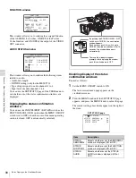
Page 89: ... then press the MENU knob or push the CANCEL PRST ESCAPE switch down to ESCAPE This cancels all changes and returns to the SHOT ID page 5 2 8 Displaying the Status Confirmation Windows You can confirm the settings or status of the camcorder on the screen by displaying the following three windows ABNORMAL window FUNCTION window AUDIO STATUS window Indications on the windows ABNORMAL window This win...

Page 90: ... as follows 1 Set the MENU ON OFF switch to ON The last accessed menu page appears on the viewfinder screen 2 Turn the MENU knob until the SET STATUS page appears and press the MENU knob to select the page The current setting of each item appears on the right of the item SET STATUS page FUNCTION FORMAT I ASSIGN 1 ATW 2 OFF T TURBO ZEBRA OFF SELECT 1 DET 70 APT 10 DET2 100 P CACHE OFF 0SEC Actual S...

Page 91: ...ob to select the page The current setting of each item appears on the right of the item GENLOCK page 4 Carry out setting operations as follows 1 Turn the MENU knob to move the b mark to GENLOCK and press the MENU knob The b mark on the left of GENLOCK changes to a z mark and the z mark on the left of the GENLOCK setting changes to a mark 2 Turn the MENU knob until OFF appears then press the MENU k...

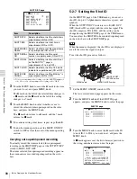
Page 92: ...es the gain of the video amplifier To set the gain values proceed as follows 1 Set the MENU ON OFF switch to ON The last accessed menu page appears on the viewfinder screen 2 Turn the MENU knob until the GAIN SW page appears then press the MENU knob to select the page The current setting of each item appears on the right of the item GAIN SW page Item Description GAIN LOW Sets the gain value corres...

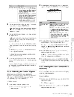
Page 93: ...ge 3 Turn the MENU knob to move the b mark to REAR BNC OUT SEL and press the MENU knob The b mark on the left of REAR BNC OUT SEL changes to a z mark and the z mark on the left of the setting changes to a mark 4 Turn the MENU knob to change the desired setting and press the MENU knob The z mark returns to a b mark and the mark on the left of the setting returns to a z mark 5 To end the menu operat...

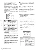
Page 94: ...e TOP menu appears 2 Turn the MENU knob to move the b mark to OPERATION and press the MENU knob If this is the first time the OPERATION menu has been displayed the CONTENTS page appears If the menu has been used before the last accessed page appears 3 If the CONTENTS page is displayed turn the MENU knob to move the b mark to OFFSET WHITE and press the MENU knob to display the OFFSET WHT page If a ...

Page 95: ...OFF switch to ON The last accessed menu page appears on the viewfinder screen 2 Turn the MENU knob until the FUNCTION 1 page appears then press the MENU knob to select to page The current settings of each item appears on the right of the item FUNCTION 1 page 3 Turn the MENU knob to move the b mark to the item corresponding to the switch to which you want to assign the function and press the MENU k...

Page 96: ...ion TEST OUT CHARACTER Assigns the function to switch whether or not text is superimposed on the video signal to be output from the TEST OUT connector MARKER Assigns the ON OFF function to display all markers 2 RE TAKE Assigns the RE TAKE function ATW Assigns the ON OFF function of auto tracing white balance RETURN VIDEO Assigns the ON OFF function to display the image of the return video signal o...

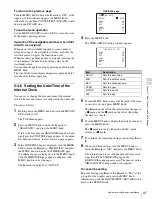
Page 97: ...e last accessed page appears 3 If the CONTENTS page is displayed turn the MENU knob to move the b mark to TIME DATE and press the MENU knob to display the TIME DATE page If a different page is displayed turn the MENU knob until the TIME DATE page appears then press the MENU knob to select the page The b mark is displayed at ADJUST TIME DATE page 4 Press the MENU knob The TIME ADJUST setting window...

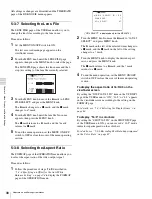
Page 98: ...io of the video output signal Proceed as follows 1 Follow the procedure of steps 1 to 3 described in 5 3 4 Specifying an Offset for the Auto White Balance Setting on page 94 to display the FORMAT page of the OPERATION menu UC J SELECT is displayed only for the MSW 970 2 Turn the MENU knob to move the b mark to 16 9 4 3 SELECT and press MENU knob The b mark on the left of the selected item changes ...

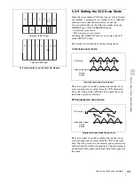
Page 99: ... using timing charts I interlace scan mode Interlace scan mode timing chart The video signal of an odd scanning line and that of an even scanning line are output from the CCD alternately Thus the timing of the odd field video signal and even field video signal are different PsF progressive scan mode Progressive scan mode timing chart The video signal of an odd scanning line and that of an even sca...

Page 100: ... of the OPERATION menu 2 Turn the MENU knob to move the b mark to SCAN MODE and press the MENU knob The b mark on the left of SCAN MODE changes to a z mark and the z mark on the left of the setting changes to a mark UC J SELECT is displayed only for the MSW 970 3 Turn the MENU knob to display PsF or 24P and press the MENU knob The z mark changes to a b mark and the mark changes to a z mark 4 To en...

Page 101: ...ization code and user code Set the country code referring to the ISO 3166 table and set the organization code and user code independently For details see UMID menu setup on page 102 Functions of UMID data The UMID data enables the following Add a globally unique ID to every shot of audio visual material The unique ID is used to detect the material source and to link it with the original source mat...

Page 102: ...to change the setting of the selected item or to display the desired value and press the MENU knob The z mark returns to a b mark and the mark returns to a z mark 6 To end the menu operation set the MENU ON OFF switch to OFF Additional information on the UMID SET menu items EX OWNERSHIP REC Specify whether to record the user data ON The user data COUNTRY CODE ORGANIZATION and USER CODE are recorde...

Page 103: ...tes enter the user code from the beginning of the 4 bytes and enter the space character 20h in the remaining strings This user code is determined by the organization The methods used depend on the organization User bits cannot be entered when no organization code has been entered INSTANCE NO Select the method for generating the numbers to be used to identify the original video images RND Random GE...

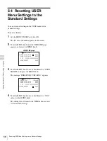
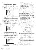
Page 104: ...knob until the USER FILE page appears and press the MENU knob USER FILE page 3 Turn the MENU knob to move the b mark to USER PRESET and press the MENU knob The message PRESET OK YES b NO appears 4 Turn the MENU knob to move the b mark to YES and press the MENU knob The settings for all items in the USER menu are reset to the standard settings F01 USER FILE USER FILE LOAD EXEC USER FILE SAVE EXEC F...

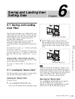
Page 105: ...xceed 128 MB For details see Memory Stick in Specifications on page 138 6 1 1 Handling the Memory Stick The Memory Stick can be inserted to or removed from the camcorder with the power turned on or off Inserting the Memory Stick Proceed as follows 1 Push the MEMORY STICK OPEN button The cover of the Memory Stick compartment opens 2 Hold the Memory Stick with the notch facing downward and the label...

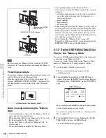
Page 106: ...eep it in its original case to ensure protection of important data When carrying the camcorder with the Memory Stick inserted close the cover of the menu operating section Avoid removing the Memory Stick from the insertion slot while the access indicator is lit Do not format the Memory Stick using a PC Formatting of Memory Sticks can be performed on the MEMORY STICK page of the FILE menu 6 1 2 Sav...

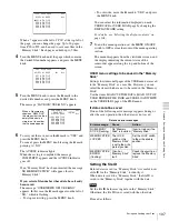
Page 107: ...order appears along the top and bottom of the screen USER menu settings to be saved in the Memory Stick Settings for items on all pages of the USER menu are saved in the Memory Stick as a user file However you can select the items which are not to be saved in the Memory Stick Use the items LOAD CUSTOM DATA LOAD OUT OF USER BEFORE FILE PAGE and USER LOAD WHITE on the USER FILE2 page of the FILE men...

Page 108: ...mory Stick overwrites the data saved in the camcorder Proceed as follows 1 Set the MENU ON OFF switch to ON The last accessed menu page appears on the screen 2 Turn the MENU knob until the USER FILE page appears then press the MENU knob Alternatively select USER FILE on the CONTENTS page 3 Turn the MENU knob to move the b mark to USER FILE LOAD and press the MENU knob The P00 USER LOAD page appear...

Page 109: ...ings made in the standard mode and ECS mode The white balance data can be loaded only when the SCENE WHITE DATA setting on the REFERENCE page of the FILE menu is ON 6 2 1 Saving a Scene File Proceed as follows to save a scene file in the camcorder memory or the Memory Stick To save a scene file in the Memory Stick insert the Memory Stick before starting the operation 1 In the TOP menu select the F...

Page 110: ...n page 111 5 To end the menu operation set the MENU ON OFF switch to OFF or close the cover of the menu operating section To return to the SCENE FILE page After the message COMPLETE is displayed move the b mark to ESC at the top right of the page by turning the MENU knob then press the MENU knob White balance setting data to be saved in the scene file The white balance setting data selected when y...

Page 111: ...U knob to move the x mark to END then press the MENU knob The SCENE FILE page appears again Carry out the procedure from step 3 in 6 2 1 Saving a Scene File page 109 The set file ID is saved together with the data Selecting the display contents You can select the items of file information to be displayed on the SCENE STORE pages P01 to P20 or the SCENE RECALL pages P01 to P20 used for saving data ...

Page 112: ...witch to OFF Loading scene files from a Memory Stick into the camcorder memory You can load up to five scene files stored in the Memory Stick into the camcorder memory in a single operation 1 After displaying the SCENE FILE page page 109 turn the MENU knob to move the b mark to SCENE RECALL and press the MENU knob A SCENE RECALL page appears 2 Turn the MENU knob until the SCENE RECALL page which c...

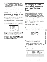
Page 113: ...nables you to save user files scene files lens files reference files and ALL files The camcorder menu system allows you to make a setting so that when a Memory Stick holding these files is inserted while in menu operating mode a menu page relating to the desired file is automatically displayed on the screen Thus you can proceed to file operation quickly This is very convenient especially when you ...

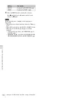
Page 114: ...cases jumping to the target page is impossible When the power is turned on after you insert a Memory Stick When OFF is selected for the M S IN JUMP TO item When any of the following menu pages is already displayed A file related page such as the USER FILE page of the FILE menu MEMORY STICK ALL FILE SCENE FILE LENS FILE REFERENCE FILE or ROM VERSION page REFER Jumps to the REFERENCE page USER 1 Jum...

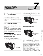
Page 115: ...y pack 1 Press the battery pack against the back of the camcorder aligning the line on the side of the battery pack with the matching line on the camcorder 2 Slide the battery pack down until its LOCK arrow points at the matching line on the camcorder Detaching the battery pack Detaching the battery pack 7 1 2 Avoiding Breaks in Operation Due to an Exhausted Battery If you use both an internal bat...

Page 116: ...er source There may be some noise on the video signal at the instant the power sources are switched 7 1 3 Using an AC Adaptor Using the AC 550 550CE AC adaptor Connect the camcorder to the AC power supply through the AC 550 550CE AC Adaptor as shown in the following figure and turn the POWER switch of the AC 550 550CE on Using an AC adaptor Using the AC DN10 AC adaptor Mount the AC DN10 on the cam...

Page 117: ...ction opposite to the barrel and the viewfinder left right positioning ring tightened Adjusting the position backward or forward Proceed as follows Adjusting the position backward or forward 1 Loosen the viewfinder front rear positioning lever and the LOCK knob 2 Slide the viewfinder longitudinally to the most convenient position 3 Tighten the viewfinder front rear positioning lever and the LOCK k...

Page 118: ...er Using the BKW 401 Viewfinder Rotation Bracket For more information refer to the BKW 401 manual 7 2 4 Detaching the Eyepiece Removing the eyepiece gives a clearer view of the screen from further away It is also easy to remove dust from the viewfinder screen and mirror when the eyepiece is detached 1 Turn the eyepiece locking ring fully counterclockwise to align the red marks on the locking ring ...

Page 119: ...enter pin on the lens and insert the lens into the mount 3 Holding the lens in place push the lens locking lever downward to mount the lens If the lens is not firmly locked it may come off while the camcorder is being used This could cause a serious accident Make sure the lens is firmly locked It is recommended that the lens mount securing rubber supplied be put on the lens locking lever as illust...

Page 120: ...lange focal length adjustment ring 4 Use manual or power zoom to set the lens to telephoto 5 Point the camera at the chart by turning the focus ring and focus on it 6 Set the zoom ring to wide angle 7 Turn the F f or F B ring until the chart is in focus being careful not to disturb the focus ring 8 Repeat steps 4 to 7 until the chart stays in focus all the way from wide angle to telephoto 9 Tighte...

Page 121: ...hone to the camcorder using the optional CAC 12 microphone holder 1 Remove the fixing screws for external microphone holder 2 Attach the CAC 12 Microphone Holder Place the microphone in the holder so that UP is at the top Tighten the screw Close the microphone holder Connect to the MIC IN connector Note External microphone AUDIO IN CH 1 CH 2 switches When the audio cable is connected to either the...

Page 122: ...le Tuner for a UHF Wireless Microphone System To use a Sony UHF wireless microphone system fit one of the following UHF portable tuners WRR 855A 855B UHF Synthesized Tuner Unit WRR 860 862 UHF Portable Tuner For each of these UHF portable tuners use the following attachment procedure For details refer to the UHF portable turner manual Fitting the WRR 855A 855B You can use the WRR 855A 855B UHF Syn...

Page 123: ...ws insert the screwdriver through the corresponding hole and tighten the screw 2 Loosen the adjustment screws 3 Adjust the tuner fitting position for a battery pack to be attached and tighten the adjustment screws to fix its position 4 Attach the mount plate supplied with the WRR 862 2 Attach the battery pack For details about attaching the battery pack see 7 1 1 Using a Battery Pack on page 115 2...

Page 124: ...AR XLR AUTO set to ON on the AUDIO 1 page of the MAINTENANCE menu the signal input to the AUDIO IN CH1 or CH2 connector is automatically selected as the signal to be recorded This is true regardless of the AUDIO IN CH 1 CH 2 switch settings This is called XLR connection automatic detection function When the XLR connection automatic detection function is set to OFF factory setting set the AUDIO IN ...

Page 125: ...n returns to the stowed position If the pin remains in the engaged position you will not be able to mount the camcorder on the tripod adaptor If the pin remains in the engaged position 7 7 Attaching Detaching the Shoulder Strap Attaching the shoulder strap Attach the supplied shoulder strap as shown below Removing the shoulder strap Note Stowed position Pin Shoulder strap post Clip Pull up the str...

Page 126: ...most convenient position 3 Bring down the lever to lock the shoulder pad in the selected position 7 9 Putting on the Rain Cover Not Supplied Attach the rain cover part number 3 191 064 02 as illustrated below You can insert and remove cassette tapes operate various switches and controls and mount the camcorder on the tripod adaptor with the rain cover attached 1 3 2 Shoulder pad Bottom When ashoul...

Page 127: ...TART button and the lens VTR button On the FUNCTION 3 page of the MAINTENANCE menu set RM REC START to RM If the same function as that of the VTR START button is assigned to the ASSIGN 1 switch or the TURBO GAIN button this setting also disables these controls To enable the camcorder VTR START button and the lens VTR button On the FUNCTION 3 page of the MAINTENANCE menu set RM REC START to CAM or ...

Page 128: ...independent data region even when you disconnect a remote control unit Set RM COMMON MEMORY to ON on the FUNCTION 3 page of the MAINTENANCE menu In this case the settings stored in the independent data region will be renewed according to the change of settings in the remote control data region Thus the settings of the paint data made with the remote control unit can be retained even if the remote ...

Page 129: ...tape Condensation does not form in the tape Condensation If you move the camcorder from a very cold place to a warm place or use it in a damp location condensation may form on the head drum Then if the camcorder is operated in this state the tape may adhere to the drum and cause a failure or even permanent damage Do the following to prevent this from happening When moving the camcorder from a cold...

Page 130: ... check that the shutter setting changes on the viewfinder screen 7 Pointing the camera at a suitable subject focus the camera and check the picture on the viewfinder screen 8 Set both of the AUDIO IN switches to FRONT and check that when sound is input to a microphone connected to the MIC IN connector on the front of the camcorder the audio level indicators appear on the viewfinder screen 9 Check ...

Page 131: ... 2 switches to FRONT 2 Set the AUDIO SELECT CH 1 CH 2 switches to AUTO 3 Set the CH 1 2 CH 3 4 switch to CH 1 2 4 Aim the microphone connected to the MIC IN connector at a suitable sound source Check that the level indications for channels 1 and 2 correspond to the sound level respectively 5 Set the AUDIO IN CH 3 and CH 4 switches to F 6 Set the CH 1 2 CH 3 4 switch to CH 3 4 7 Aim the microphone ...

Page 132: ...y panel and audio level indicators in the viewfinder reflect the changing sound level the function of the XLR connection automatic detection works correctly If it does not reflect the changing sound level the function of the XLR connection automatic detection function is off Set REAR XLR AUTO to ON on the AUDIO 1 page of the MAINTENANCE menu If it does not reflect even after making this setting th...

Page 133: ...assembling the eyepiece for cleaning 1 Detach the eyepiece from the viewfinder barrel For the detaching procedure see 7 2 4 Detaching the Eyepiece on page 118 2 Remove the eyecup from the eyecup holder 3 Remove the protecting filter together with the packing ring from inside the eyecup holder 4 Detach the protecting filter from the packing ring Fog proof filter Depending on the temperature and hum...

Page 134: ...ur Sony service representative SERVO Lit Servo lock lost Recording continuous but may be substandard Turn off the power and contact your Sony service representative This indication may be given momentarily when the tape starts moving but this does not indicate a problem HUMID Lit 1 Condensa tion on the optical pickup Recording continues but stops if the tape sticks to the head drum Playback fast f...

Page 135: ...S indicates the shooting interval MANU INTERVAL FRAME Indicates the camera is in the single shot mode of the Manual Interval Rec mode FRAME indicates the number of frames INTERVAL S M H FRAME Indicates the camera is in the consecutive mode of the Manual Interval Rec mode S M H indicates the trigger interval and FRAME indicates the number of frames 40Mbps 30Mbps Indicates the recording bit rates Wh...

Page 136: ...mera Section General Imager 2 3 inch type CCD with 1 000 000 pixels Effective picture elements 980 H 988 V with MSW 970 980 H 1164 V with MSW 970P Imager Configuration RGB 3 CCDs Spectral system F1 4 prism system with quartz filter Built in filters CC filter A Cross filter B 3200K C 4300K D 6300K ND filter 1 Clear 2 1 4 ND 3 1 16 ND 4 1 64 ND Lens mount Special bayonet mount Sensitivity F11 standa...

Page 137: ...ck machine Frequency response 20 Hz to 20 kHz 0 5 1 0 dB Dynamic range 85 dB min emphasis ON Distortion THD 0 08 max Cross talk 70 dB max Wow and flutter Below measurable limit Input output connectors Signal inputs AUDIO IN CH1 CH2 XLR type 3 pin female 60 dBu 50 dBu 4 dBu 0 dBu 0 775 Vrms MIC IN XLR type 3 pin female 60 dBu 50 dBu GENLOCK IN BNC type 1 0 Vp p 75 Ω unbalanced TC IN BNC type 0 5 V ...

Page 138: ...rs are male and 5 pin A converting adaptor may be required depending on the audio equipment to be connected to the camcorder Extension boards CBK FC01 Pull Down 24P Board for the MSW 970 only CBK SD01 SDI Output Board MSDW 903 Picture Cache Board MSDW 904 Analog Composite Input Board Equipment for maintenance and easier handling BCT D12CL Cleaning Cassette LC DN7 Hard Carrying Case LC DS300SFT Sof...

Page 139: ...fer from what is shown in the manual USER menu No Page Item Settings Default Description a 01 OUTPUT SEL REAR BNC OUT SEL VBS SDI VBS See 5 3 2 Selecting the Output Signals on page 93 a 02 TEST OUT TEST OUT MARKER OFF ON OFF Selects whether or not the marker signal is mixed to the output signal from the TEST OUT connector TEST OUT VFDISP OFF ON OFF Selects whether or not the VF DISP display signal...

Page 140: ...NT M INT OFF See 3 2 4 Starting a Shoot with a Few Seconds of Pre Stored Picture Data Picture Cache Function with MSDW 903 on page 41 CACHE CACHE REC TIME 0 1 2 3 4 5 6 8 SEC 0 SEC A INT TAKE TOTAL TIME 5 10 15 20 30 40 50 MIN 1 2 3 4 5 7 10 15 20 30 40 50 70 100 H 5 MIN See 3 2 5 Shooting Picture at Intervals Interval Rec Function with MSDW 903 on page 43 A INT REC TIME 5 10 15 20 30 40 50 SEC 1 ...

Page 141: ...to 99 0 Sets the level at which the LOW LIGHT function becomes effective VF BATT WARNING 10 20 10 Sets the threshold value of remaining battery capacity to make the remaining capacity indication flash a 05 VF DISP 1 VF DISP OFF ON OFF See 5 2 2 Selecting the Display Items on page 84 VF DISP MODE 1 2 3 3 DISP EXTENDER OFF ON ON DISP FILTER OFF ON ON DISP WHITE OFF ON ON DISP GAIN OFF ON ON DISP SHU...

Page 142: ...20 MSW 970 72 Adjusts the height from the center to top or bottom of the box cursor 1 to 142 MSW 970P 85 USER BOX H POS 461 to 461 0 Adjusts the H position of the center USER BOX V POS 118 to 118 MSW 970 0 Adjusts the V position of the center 141 to 140 MSW 970P CENTER H POS 48 to 47 0 Adjusts the H position of the center marker CENTER V POS 15 to 14 0 Adjusts the V position of the center marker a...

Page 143: ...ATE OFF ON OFF See 5 2 6 Recording Shot Data Superimposed on the Color Bars on page 87 SHOT TIME OFF ON OFF SHOT MODEL NAME OFF ON OFF SHOT SERIAL NO OFF ON OFF SHOT ID SEL OFF ID 1 ID 2 ID 3 ID 4 OFF SHOT 16 9 ID OFF ON OFF SHOT BLINK CHARA OFF ON OFF a 15 SET STATUS STATUS ABNORMAL OFF ON ON See 5 2 8 Displaying the Status Confirmation Windows on page 89 STATUS FUNCTION OFF ON ON STATUS AUDIO OF...

Page 144: ...en a lens having serial transmission ability is mounted F ID Display only L ID Display only To show the lens specific ID when a serial lens is connected L MF Display only To show the name of the lens manufacturer when a serial lens is connected 19 FORMAT 16 9 4 3 SELECT 16 9 4 3 16 9 See 5 3 8 Selecting the Aspect Ratio on page 98 SCAN MODE I PsF 24P 24P is selectable only when CBK FC01 is connect...

Page 145: ...ing UMID Data on page 101 COUNTRY CODE 4 byte alphanumeric strings ORGANIZATION 4 byte alphanumeric strings USER CODE 4 byte alphanumeric strings INSTANCE NO RND GEN RND TIME ZONE 00 00 to 25 1A to1F 2A to 2F 32 3A to 3F 00 MACHINE n USER menu No Page Item Settings Default Description ...

Page 146: ... A 99 to 99 0 Adjusts the value more precisely when the color temperature adjustment through COLOR TEMP is not satisfactory R GAIN A 99 to 99 0 Only the value of R GAIN is changed B GAIN A 99 to 99 0 Only the value of B GAIN is changed D5600K A OFF ON OFF Turns the WHITE A electronic 5600K filter on off COLOR TEMP B Display color temperature 3200 Sets the color temperature of WHITE B COLOR FINE B ...

Page 147: ...B BLACK GAMMA 99 to 99 0 Sets the correction curve of the B black gamma TEST OUT SELECT ENC R G B ENC Selects the output signal of TEST OUT connector P06 KNEE KNEE OFF ON ON Turns the knee correction circuit on off KNEE POINT 50 to 109 85 0 Sets the knee point level KNEE SLOPE 99 to 99 0 Set the knee slope level KNEE SATURATION OFF ON ON Turns the knee saturation function on off KNEE SAT LEVEL 99 ...

Page 148: ...f the V DTL signal H V CONTROL MODE H V V V Select the operation mode of DETAIL H V RATIO on the DETAIL 1 page H V H and V both enabled V V DTL only enabled P10 SKIN DETAIL SKIN DETAIL ALL OFF ON OFF Turns on all of 1 2 and 3 of the color detail function SKIN DETECT Moves to color detection page EXEC Executes the color detail function SKIN AREA IND OFF ON OFF Turns the zebra indication on off in t...

Page 149: ...OFF ON OFF Turns the multi matrix correction function on off MATRIX AREA IND OFF ON OFF Turns the zebra indication on off in the area corresponding to the currently selected setting MATRIX COLOR DET Moves to color detection page EXEC Detects color MTX MULTI AXIS B B MG MG MG R R YL YL YL G G G CY CY B B Selects the axis for which the multi matrix correction function can be changed MTX MULTI HUE 99...

Page 150: ...rve in the low luminance part Y BLK GAM RANGE LOW L MID H MID HIGH HIGH Sets the luminance level at which the Y black gamma becomes effective P15 SCENE FILE 1 Recalls the scene file saved in the memory of the camcorder 2 3 4 5 STANDARD Clears all current detail adjusted settings and switch settings and returns the settings to the standard settings saved in the reference file SCENE RECALL Recalls t...

Page 151: ...E SAW PARA OFF ON ON Turns white shading Saw and Parabola compensation on and off M02 BLK SHADING BLK SHAD CH SEL R G B TEST R Selects the channel adjusted by this menu If TEST is selected the setting is the same as the setting of TEST OUT SELECT TEST OUT SELECT ENC R G B ENC Selects the signal output to the TEST OUT connector R G B BLK H SAW 99 to 99 0 For the H Saw black shading compensation R G...

Page 152: ... at which the battery ends and the camcorder stops operation just before the battery ends BATT REMAIN DISP 1 2 3 1 1 Standard mode 2 LCD remaining indication mode One x on the LCD indicates 10 for a battery classified in Others EXT DC type 3 ANTON mode Remaining detection of the ANTON type is made even for a battery classified in SONY type M05 AUDIO 1 V A OUT FF REW EE PB EE Selects the video outp...

Page 153: ...nd on CH 2 select which control is to be used for the level adjustment SIDE 2 Adjust it with the LEVEL control right side on the side panel FRONT Adjust it with the MIC LEVEL control on the front panel F S2 It can be adjusted using either the LEVEL control right side or the MIC LEVEL control The two controls are linked to each other REAR1 WRR LEVEL SIDE1 FRONT F S1 SIDE 1 Selects any of these cont...

Page 154: ...hes with the time data of the user bits of an external time code UBIT GROUP ID 000 101 000 Selects the UBIT GROUP ID VITC INS LINE 1 12 to 19 H MSW 970 16H Selects the line into which VITC is to be inserted 9 to 22 H MSW 970P 19H VITC INS LINE 2 12 to 19 H MSW 970 18H Selects the line into which VITC is to be inserted 9 to 22 H MSW 970P 21H M09 VTR MODE REC TALLY BLINK OFF ON ON Turns the tally il...

Page 155: ...rite a mark when the ND filter or CC filter is changed in recording on off SHUTTER CHG MARK OFF ON ON Turns the function to write a mark when the shutter speed or shutter mode is changed in recording on off WHITE CHG MARK OFF ON ON Turns the function to write a mark when the white balance is changed in recording on off FLASH MARK OFF ON ON Turns the function to write a mark when an extreme luminun...

Page 156: ...auto iris target value IRIS APL RATIO 99 to 99 0 Adjusts the mix ratio of auto iris detection peak value and average value IRIS VAR WIDTH 20 to 465 245 Sets the width and height of detection frame when the auto iris detection window is set to VAR IRIS VAR HEIGHT 17 to 120 MSW 970 72 Sets the height of detection frame when the auto iris detection window is set to VAR 20 to 142 MSW 970P 85 IRIS VAR ...

Page 157: ...setting EXT VTR REC CTL OFF ON OFF Selects whether to synchronize recording with an external VTR via a CCZ cable when the CA 702 is connected M16 FUNCTION 4 SET DISP MODE SEC DEG SEC Selects whether to display the shutter speed in seconds or degrees AWB FIXED AREA OFF ON OFF Selects whether or not to perform AWB for all pixels in the rectangular area of 25 by 25 M17 GENLOCK GENLOCK OFF ON ON Turns...

Page 158: ...158 Specifications Appendixes M20 VANC RX UMID LINE 0 12 13 15 to 19 MSW 970 0 Selects the line on which the UMID is to be recorded 0 9 10 12 to 18 MSW 970P No Page Item Settings Default Description ...

Page 159: ...SER menu to the factory default state LOAD CUSTOM DATA OFF ON OFF Selects whether to read the USER MENU CUSTOMIZE settings to be loaded by USER FILE LOAD LOAD OUT OF USER OFF ON OFF Selects whether to read pages not registered by USER FILE LOAD BEFORE FILE PAGE OFF ON OFF Selects whether to read data after USER FILE pages by USER FILE LOAD USER LOAD WHITE OFF ON OFF Selects whether to read white b...

Page 160: ...ion of lens file center marker LENS CENTER V 15 to 14 0 For the vertical position compensation of lens file center marker TEST OUT SELECT ENC R G B ENC Selects signal output to TEST OUT connector LENS R FLARE 99 to 99 0 Adjusts the lens file flare R LENS G FLARE 99 to 99 0 Adjusts the lens file flare G LENS B FLARE 99 to 99 0 Adjusts the lens file flare B LENS W R OFST 99 to 99 0 Adjusts the R com...

Page 161: ...161 Specifications Appendixes F10 TELE FILE TELE FILE CLEAR EXEC See 3 4 Tele File System on page 53 TELE FILE MARK OK NG KP OK ID SIZE REMAIN STATUS No Page Item Settings Default Description ...

Page 162: ...G 2 Displays the total time the drum has rotated reset possible TAPE RUNNING 2 Displays the accumlated time the tape has run reset possible OPERATION 2 Display the time that the unit has been powered reset possible THREADING 2 Displays the number of time of tape threading reset possible D02 TIME DATE ADJUST See 5 3 6 Setting the Date Time of the Internal Clock on page 97 HOUR MIN SEC YEAR MONTH DA...

Page 163: ...emory Stick Duo with your product Note on data read write speed Data read write speed may vary depending on the combination of the Memory Stick and Memory Stick compliant product you use What is MagicGate MagicGate is copyright protection technology that uses encryption technology Before using a Memory Stick When you set the Memory Stick erasure prevention switch to LOCK data cannot be recorded ed...

Page 164: ...ccordance with copyright and other applicable laws The Memory Stick application software may be modified or changed by Sony without prior notice Note that there are certain restrictions on recording stage performances and other entertainment events even if they are recorded for personal use only Memory Stick and MagicGate Memory Stick are trademarks of Sony Corporation Memory Stick Duo and are tra...

Page 165: ...r 19 C Camera operator tally indicator 22 CANCEL PRST ESCAPE switch 27 cassette loading 34 unloading 35 CBK SD01 52 CC filter 61 CCD image sensors 135 CH 1 2 CH 3 4 switch 18 Cleaning video heads 133 viewfinder 133 color temperature 93 Condensation 129 continues recording 37 Continuous Trigger mode 47 CONTRAST control 21 D DATA DISPLAY switch 29 Date Time of the Internal Clock 97 DC IN connector 1...

Page 166: ...rogressive scan mode 99 PsF mode 99 Pull down mode 100 R Rain Cover 126 REAR TALLY indicator 31 REC indicator 33 Recording Review 52 recording start mark 38 41 REFERENCE 160 reference file 113 REMOTE connector 24 RESET button 29 RE TAKE function 50 return video signal 91 REW button and indicator 25 ROM VERSION 162 S SAVE indicator 33 SCENE FILE 150 159 scene file 109 loading 111 saving 109 SCENE F...

Page 167: ...8 Viewfinderfront rearpositioninglever 22 Viewfinder left right positioning ring 22 viewfinder position 117 Viewfinder Rotation Bracket 118 Viewfinder stopper 22 VTR MODE 154 VTR operation status and status indicators 32 VTR SAVE STBY switch 25 VTR START button 25 W Warning indicator 33 WARNING indicator 31 WHITE 146 WHITE BAL switch 23 white balance 61 White flecks 135 WHITE page 94 WHT SHADING 1...

Page 168: ...168 Index Index ...

Page 169: ... for use by the purchasers of the equipment described in this manual Sony Corporation expressly prohibits the duplication of any portion of this manual or the use thereof for any purpose other than the operation or maintenance of the equipment described in this manual without the express written permission of Sony Corporation ...

Page 170: ...Sony Corporation MSW 970 970P SY 3 863 920 03 1 Printed in Japan 2006 11 13 2005 ...

Reviews: