57
Recording Video Signals from External Equipment (When Using an MSDW-904)
Chapt
er
3
Re
c
o
rdin
g and Pl
a
y
b
a
c
k
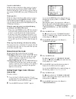
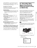
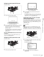
the OPERATION menu is displayed on the viewfinder
screen.
2
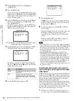
Turn the MENU knob to move the
b
mark to EXT
OUTPUT DELAY, then push the MENU knob.
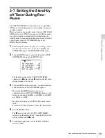
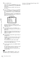
The
b
mark on the left of “EXT OUTPUT DELAY”
changes to the
z
mark, and the
z
mark to the left of
the setting changes to the ? mark.
1) Since the V sync signal is output with delay of 8 horizontal lines, any
external equipment connected after the second one are not
synchronized with the camcorder when interconnecting multiple
camcorders for recording.
2) Even though the pictures are displayed at lower position on the
monitor, the video signals are correctly recorded on the tape.
3
Turn the MENU knob until the desired delay mode
appears.
4
Push the MENU knob.
The
z
mark on the left of “EXT OUTPUT DELAY”
returns to the
b
mark and the ? mark to the left of the
setting returns to the
z
mark.
5
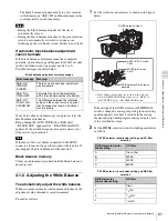
To end menu operations, set the MENU ON/OFF
switch to OFF.
The menu disappears from the viewfinder screen, and
the display indicating the current status of the
camcorder appears along the top and bottom of the
viewfinder screen.
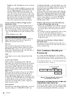
Removing the setup signal from the
external video signals (MSW-970 only)
When the UC/J SELECT item is set to UC on the
FORMAT page of the OPERATION menu, the SETUP
REMOVE item appears on the SOURCE SEL page of the
USER menu.
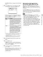
The SETUP REMOVE item allows you to eliminate the
setup signal from the external video signals within a range
of from 0 to 10% in 0.5% steps. The elimination range has
been set to 7.5% at the factory.
• When the UC/J SELECT item is set to UC on the
FORMAT page of the OPERATION menu, a 7.5% setup
signal is automatically added to the composite video
signal output from the TEST OUT connector.
• Even when the GENLOCK ON/OFF item is set to
“OFF” on the GENLOCK page of the MAINTENANCE
menu, the camcorder is automatically synchronized with
the external reference video signal when the external
video signal is input to the GENLOCK IN connector in
EXT mode. When the setting is switched to CAM mode,
or when no signals are input to the GENLOCK IN
connector even in EXT mode, the camcorder is reset to
the original setting.
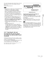
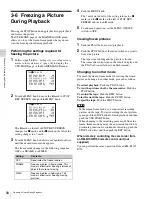
Item
Contents
SYNC
Outputs the video signals including the
V sync signal, which are delayed by 8
horizontal lines against the input signals
to the GENLOCK IN connector, from the
TEST OUT connector or the VIDEO
OUT connector. The pictures are
displayed at the correct position on the
video monitor.
1)
VIDEO
Outputs the video signals, excluding the
V sync signal, with delayed by 8
horizontal lines against the input signals
to the GENLOCK IN connector, from the
TEST OUT connector or the VIDEO
OUT connector. The V sync signal is
the same as the V sync signal input to
the GENLOCK IN connector. On the
video monitor, pictures are displayed
lowered by 8 horizontal lines.
2)
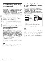
REC VIDEO SOURCE: EXT
EXT OUTPUT DELAY: SYNC
SETUP REMOVE : 7.5%
21 SOURCE SEL TOP
Notes
Summary of Contents for MSV-970
Page 5: ...5 ...
Page 168: ...168 Index Index ...
Page 170: ...Sony Corporation MSW 970 970P SY 3 863 920 03 1 Printed in Japan 2006 11 13 2005 ...

