– 11 –
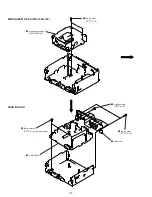
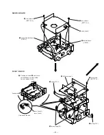
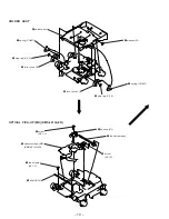
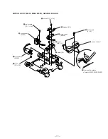
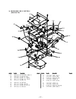
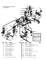
MOTOR ASS’Y (M901, M902, M903), SENSOR BOARD
2
two screws
(2
×
8)
3
sensor board
5
bracket (SL)
6
motor ass’y
(M902)
7
screw
(B2
×
3)
8
base (SL)
1
Remove the solders
of motor (M901, M902, M903).
0
motor ass’y
(M901)
9
two screws
(P1.7
×
1.8)
4
screw (P1.7
×
1.8)
!¡
screw
(P2
×
2.2)
!™
motor ass’y
(M903)
Summary of Contents for MDX-C670
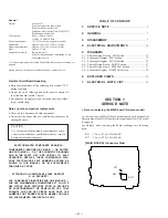
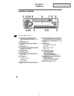
Page 3: ... 3 SECTION 2 GENERAL This section is extracted from MDX C670 instruction manual ...
Page 4: ... 4 ...
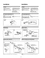
Page 5: ... 5 ...
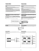
Page 6: ... 6 ...
Page 15: ......
Page 16: ......
Page 17: ......
Page 18: ......
Page 19: ......
Page 48: ......
Page 49: ......
Page 50: ......
Page 51: ......
Page 52: ......
Page 53: ......
Page 54: ......
Page 55: ......
Page 56: ......
Page 57: ......
Page 58: ......
Page 59: ......


