– 15 –
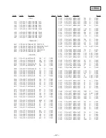
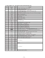
3-3. MAIN BOARD IC751 MN1883220Y5D1 (TUNER CONTROLLER) (MDX-C670RDS)
1
RD
I
Read pulse input terminal of data (D0 to D3) (Not used in this set) (open)
2
BUSY
I
BUSY output monitor terminal (Not used in this set) (open)
3
D3
I/O
Command input/output (Not used in this set) (open)
4
D2
I/O
Command input/output (Not used in this set) (open)
5
D1
I/O
Command input/output (Not used in this set) (open)
6
D0
I/O
Command input/output (Not used in this set) (open)
7
VDD
–
Power supply (+5 V)
8
X1
O
System clock input (8.0 MHz)
9
X2
I
System clock output (8.0 MHz)
10
GND
–
Ground
11
XI
I
Connected to the GND
12
–
–
Not used (open)
13
XO
O
Connected to the GND
14
RESET
I
Reset input
15
RDS-CLK
I
RDS serial clock input pin
16
BU-IN
I
BATT voltage detection pin
17
BUSON
I
BUS ON control input pin
18-29
–
–
Not used (open)
30
RDS-DATA
I
RDS serial data input pin
31
–
–
Connected to the GND
32-35
–
–
Not used (open)
36
–
–
Connected to the GND
37
–
–
Connected to the GND
38
PLL-DI
I
PLL serial data input pin
39
PLL-DO
O
PLL serial data output pin
40
PLL-CLK
O
PLL serial clock output pin
41
CE
O
PLL serial chip enable output pin
42
RQ
O
Bus request signal output pin
43
LINK-OFF
O
Link-off signal output pin (for SONY BUS)
44
SCK
I
Serial clock input pin (for SONY BUS)
45
SI
I
Serial data input pin (for SONY BUS)
46
SO
O
Serial data output pin (for SONY BUS)
47
VDD
–
Power supply (+5 V)
48
AVDD
–
Power supply for A/D converter (+5 V)
49
VREF
–
Reference power supply (+5 V)
50, 51
–
–
Connect to the GND
52
SRAM-RST
I
SRAM reset signal input pin
53
MUTE-SEL
I
Muting select signal input pin (Not used in this set) (Connected to the GND)
54
MS-1
I
Destination setting pin (Not used in this set) (Connected to the GND)
55
MS-2
I
Destination setting pin (Not used in this set) (Connected to the GND)
56
AM-S.METER
I
AM signal meter voltage detection pin
57
FM-S.METER
I
FM signal meter voltage detection pin
58
–
–
Connected to the GND
Pin No.
Pin Name
I/O
Function
Summary of Contents for MDX-C670
Page 3: ... 3 SECTION 2 GENERAL This section is extracted from MDX C670 instruction manual ...
Page 4: ... 4 ...
Page 5: ... 5 ...
Page 6: ... 6 ...
Page 15: ......
Page 16: ......
Page 17: ......
Page 18: ......
Page 19: ......
Page 48: ......
Page 49: ......
Page 50: ......
Page 51: ......
Page 52: ......
Page 53: ......
Page 54: ......
Page 55: ......
Page 56: ......
Page 57: ......
Page 58: ......
Page 59: ......

