– 16 –
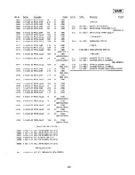
59
–
–
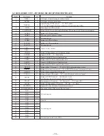
Connected to the GND
60
–
–
Connected to the GND
61
TU-ON
O
Tuner system power supply control pin
62
–
–
Not used (open)
63
SEEK.OUT
O
Seek signal output pin
64
AM.ON
O
AM power supply control pin (Not used in this set) (open)
65
FM.ON
O
FM power supply control pin
66
TUNER-MUTE
O
Tuner muting signal output pin
67
AF-SEEK
O
AF seek signal output pin
68
–
–
Not used (open)
69
–
–
Not used (open)
70
ST-IN/MONO
I
Stereo detection signal input pin
71
SD-IN
I
Station detection signal input pin
72-75
–
–
Not used (open)
76
PDWN
O
Power down terminal (Not used in this set) (open)
77
TIM.RESET
O
Reset/power down terminal (Not used in this set) (open)
78
TIM.CE
O
Data permission/prohibition setting through D0 to D3
“H”: permission (Not used in this set) (open)
79
TIM.CE
O
Data permission/prohibition setting through D0 to D3
“L”: permission (Not used in this set) (open)
80
WR
I
Write pulse input terminal of data (D0 to D3) (Not used in this set) (open)
Pin No.
Pin Name
I/O
Function
Sony Corporation
Personal & Mobile Communication Company
97E0581-1
Printed in Japan © 1997.5
Published by Quality Assurance Dept.
9-925-530-81
MDX-C670/C670RDS
Summary of Contents for MDX-C670
Page 3: ... 3 SECTION 2 GENERAL This section is extracted from MDX C670 instruction manual ...
Page 4: ... 4 ...
Page 5: ... 5 ...
Page 6: ... 6 ...
Page 15: ......
Page 16: ......
Page 17: ......
Page 18: ......
Page 19: ......
Page 48: ......
Page 49: ......
Page 50: ......
Page 51: ......
Page 52: ......
Page 53: ......
Page 54: ......
Page 55: ......
Page 56: ......
Page 57: ......
Page 58: ......
Page 59: ......


