— 3 —
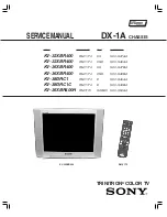
KV-32XBR400/36XBR400/36XBR400H/38DRC1/38DRC1C
Section
Title
Page
Warnings and Cautions ...................................................................................................................................... 4
Self-Diagnostic Function .................................................................................................................................... 4
Safety Check-Out Instructions ............................................................................................................................ 7
1.
GENERAL
........................................................................................................................................................... 8
2.
DISASSEMBLY
2-1.
Rear Cover Removal ............................................................................................................................. 13
2-2.
Chassis Assembly Removal .................................................................................................................. 13
2-3.
Service Position ..................................................................................................................................... 13
2-4.
Picture Tube Removal ............................................................................................................................ 14
3.
SET-UP ADJUSTMENTS
3-1.
Beam Landing ....................................................................................................................................... 15
3-2.
V-Pin and V-Cen Adjustment .................................................................................................................. 16
3-3.
Convergence ......................................................................................................................................... 16
3-4.
Focus Adjustment .................................................................................................................................. 18
3-5.
Screen (G2) ............................................................................................................................................ 18
3-6.
Picture Quality Adjustments ................................................................................................................... 18
3-7.
White Balance Adjustments ................................................................................................................... 20
3-8.
Raster Center Adjustment ..................................................................................................................... 21
3-9.
Picture Distortion Adjustments ............................................................................................................... 21
3-9-1. NTSC (DRC) Full Mode Adjustment ...................................................................................................... 21
4.
SAFETY RELATED ADJUSTMENTS
RV8001, 8002, 8003 Confirmation Method and HV Service Adjustments ....................................... 23
5.
CIRCUIT ADJUSTMENTS
5-1.
Setting the Service Adjustment Mode ................................................................................................... 24
5-2.
Memory Write Confirmation Method ...................................................................................................... 24
5-3.
Adjustment Buttons and Indicators ........................................................................................................ 24
5-4.
Service Data Lists .................................................................................................................................. 25
6.
DIAGRAMS
6-1.
Block Diagram ....................................................................................................................................... 55
6-2.
Circuit Board Location ........................................................................................................................... 55
6-3.
Printed Wiring Boards and Schematic Diagrams .................................................................................. 55
• A Board .............................................................................................................................................. 58
• C Board .............................................................................................................................................. 60
• S Board .............................................................................................................................................. 61
• HA Board ........................................................................................................................................... 61
• BC Board ........................................................................................................................................... 62
• W Board ............................................................................................................................................. 62
• B Board .............................................................................................................................................. 63
• HB Board ........................................................................................................................................... 63
• D Board .............................................................................................................................................. 68
• U Board .............................................................................................................................................. 72
6-4.
Semiconductors ..................................................................................................................................... 73
7.
EXPLODED VIEW
7-1. Chassis .................................................................................................................................................. 7
6
7-2. Picture Tube ........................................................................................................................................... 7
8
8. ELECTRICAL PARTS LIST
................................................................................................................................................
81
TABLE OF CONTENTS
Summary of Contents for KV-32XBR400
Page 53: ...KV 32XBR400 36XBR400 36XBR400H 38DRC1 38DRC1C 53 NOTES ...
Page 54: ...KV 32XBR400 36XBR400 36XBR400H 38DRC1 38DRC1C 54 NOTES ...
Page 75: ... 75 KV 32XBR400 36XBR400 36XBR400H 38DRC1 38DRC1C NOTES 6556 03N 43N 03S 43S 13N 53N NOTES ...
Page 80: ... 80 KV 32XBR400 36XBR400 36XBR400H 38DRC1 38DRC1C 6556 03N 43N 03S 43S 13N 53N NOTES NOTES ...
Page 119: ...KV 32XBR400 36XBR400 36XBR400H 38DRC1 38DRC1C 119 NOTES ...
Page 120: ...KV 32XBR400 36XBR400 36XBR400H 38DRC1 38DRC1C 120 NOTES ...


