— 3 —
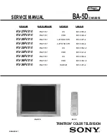
KV-27FV310/29FV310/32FV310/36FV310
Specifi cations ............................................................................................................................................. 4
Warning and Cautions ................................................................................................................................ 5
Safety Check-Out ....................................................................................................................................... 6
Self-Diagnostic Function............................................................................................................................. 7
SECTION 1: DISASSEMBLY........................................................................................................................... 10
1-1. Rear Cover Removal........................................................................................................................ 10
1-3. Service Position REMOVAL ............................................................................................................. 10
1-2. Chassis Assembly Removal............................................................................................................. 10
1-4. Picture Tube Removal.......................................................................................................................11
Anode Cap Removal Procedure........................................................................................................11
SECTION 2: SET-UP ADJUSTMENTS............................................................................................................ 12
2-1. Beam Landing .................................................................................................................................. 12
2-2. Convergence.................................................................................................................................... 13
2-3. Focus ............................................................................................................................................... 14
SECTION 3: SAFETY RELATED ADJUSTMENTS......................................................................................... 16
3-1.
X
RV8002 Confi rmation Method (HV Hold-Down Confi rmation) and Readjustments.................... 16
SECTION 4: CIRCUIT ADJUSTMENTS.......................................................................................................... 17
4-1. Setting the Service Adjustment Mode .............................................................................................. 17
4-2. Memory Write Confi rmation Method ................................................................................................ 17
4-3. Remote Adjustment Buttons and Indicators ..................................................................................... 17
4-4. Service Data Lists ............................................................................................................................ 18
4-5. ID Map Table .................................................................................................................................... 25
4-6. A Board Adjustments........................................................................................................................ 26
SECTION 5: DIAGRAMS................................................................................................................................. 29
5-1. Circuit Boards Location .................................................................................................................... 29
5-2. Printed Wiring Board and Schematic Diagram Information.............................................................. 29
5-3. Block Diagrams ................................................................................................................................ 30
5-4. Schematics and Supporting Information .......................................................................................... 34
A Board Schematic Diagram ............................................................................................................ 34
HR Board Schematic Diagram ......................................................................................................... 39
BC Board Schematic Diagram ......................................................................................................... 40
P Board Schematic Diagram............................................................................................................ 43
Y Board Schematic Diagram............................................................................................................ 45
HU Board Schematic Diagram ......................................................................................................... 46
D Board Schematic Diagram............................................................................................................ 47
V Board Schematic Diagram............................................................................................................ 49
GK Board Schematic Diagram ......................................................................................................... 51
C Board Schematic Diagram............................................................................................................ 54
5-5. Semiconductors................................................................................................................................. 56
SECTION 6: EXPLODED VIEWS .................................................................................................................... 57
6-1. Chassis (KV-27FV310/29FV310 ONLY) .......................................................................................... 57
6-2. Picture Tube (KV-27FV310/29FV310 ONLY) .................................................................................. 58
6-3. Chassis (KV-32FV310 ONLY) .......................................................................................................... 59
6-4. Picture Tube (KV-32FV310 ONLY)................................................................................................... 60
6-5. Chassis (KV-36FV310 ONLY) .......................................................................................................... 61
6-6. Picture Tube (KV-36FV310 ONLY)................................................................................................... 62
SECTION 7: ELECTRICAL PARTS LIST........................................................................................................ 63
TABLE OF CONTENTS
SECTION TITLE
PAGE
Summary of Contents for KV-27FV310 - 27" Fd Trinitron Wega
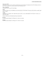
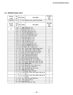
Page 18: ... 18 KV 27FV310 29FV310 32FV310 36FV310 4 4 SERVICE DATA LISTS ...
Page 19: ... 19 KV 27FV310 29FV310 32FV310 36FV310 SERVICE DATA LISTS ...
Page 20: ... 20 KV 27FV310 29FV310 32FV310 36FV310 SERVICE DATA LISTS ...
Page 21: ... 21 KV 27FV310 29FV310 32FV310 36FV310 SERVICE DATA LISTS ...
Page 22: ... 22 KV 27FV310 29FV310 32FV310 36FV310 SERVICE DATA LISTS ...
Page 23: ... 23 KV 27FV310 29FV310 32FV310 36FV310 SERVICE DATA LISTS ...
Page 24: ... 24 KV 27FV310 29FV310 32FV310 36FV310 SERVICE DATA LISTS ...
Page 30: ... 30 KV 27FV310 29FV310 32FV310 36FV310 5 3 BLOCK DIAGRAM PAGE 1 OF 4 ...
Page 31: ... 31 KV 27FV310 29FV310 32FV310 36FV310 BLOCK DIAGRAM PAGE 2 OF 4 ...
Page 32: ... 32 KV 27FV310 29FV310 32FV310 36FV310 BLOCK DIAGRAM PAGE 3 OF 4 ...
Page 33: ... 33 KV 27FV310 29FV310 32FV310 36FV310 BLOCK DIAGRAM PAGE 4 OF 4 ...
Page 103: ......
Page 158: ......
Page 159: ......
Page 216: ......
Page 217: ......
Page 266: ......


