— 17 —
KV-27FV310/29FV310/32FV310/36FV310
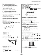
4-1. SETTING THE SERVICE ADJUSTMENT
MODE
1. Standby mode (Power off).
2. Press the following buttons on the remote commander within a
second of each other:
DISPLAY
Channel 5
Sound Volume +
Power
SERVICE ADJUSTMENT MODE ON
Disp.
(Item)
Item
data
0
VP
HSIZ
7
TV
Item
order
SERVICE
Mode
1. The CRT displays the item being adjusted.
2. Press 1 or 2 on the Remote Commander to select the item.
3. Press 3 or 6 on the Remote Commander to change the data.
4. Press MUTING then ENTER to write into memory.
SERVICE ADJUSTMENT MODE MEMORY
Disp.
(Item)
Item
data
SERVICE
0
VP
HSIZ
7
TV
Item
order
1. Press 8 then ENTER on the Remote Commander to initialize.
Disp.
(Item)
Item
data
WRITE
0
VP
HSIZ
7
TV
Item
order
Carry out Step 1 when adjusting
ID’s 0-7 and when replacing and
adjusting IC003.
2. Press MUTING then ENTER to write into memory.
3. DO NOT turn off set until SERVICE appears.
4-2. MEMORY WRITE CONFIRMATION
METHOD
1. After adjustment, pull out the plug from the AC outlet, then replace
the plug in the AC outlet again.
2. Turn the power switch ON and set to Service Mode.
3. Call the adjusted items again to confi rm they were adjusted.
4-3. REMOTE ADJUSTMENT BUTTONS AND
INDICATORS
SECTION 4: CIRCUIT ADJUSTMENTS
ELECTRICAL ADJUSTMENTS BY REMOTE COMMANDER
Use the Remote Commander (RM-Y181) to perform the circuit adjustments in this section.
Test Equipment Required:
1. Pattern generator 2. Frequency counter 3. Digital multimeter 4. Audio oscillator
RM-Y181
MUTING
(Enter into
memory)
POWER
(Service Mode)
2
(Device Item Up)
4
Disp. (Item down)
8
(Initialize)
3
Item
(Data up)
1
Disp. (Item up)
5
(Device item
down)
ENTER
(Enter into
memory)
0
(Remove from
memory)
VOLUME (+)
(Service Mode)
6
Item
(Data down)
DISPLAY
(Service Mode)
Summary of Contents for KV-27FV310 - 27" Fd Trinitron Wega
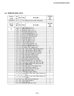
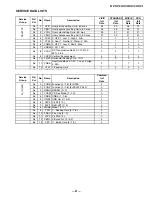
Page 18: ... 18 KV 27FV310 29FV310 32FV310 36FV310 4 4 SERVICE DATA LISTS ...
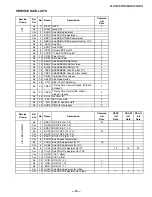
Page 19: ... 19 KV 27FV310 29FV310 32FV310 36FV310 SERVICE DATA LISTS ...
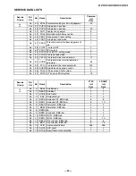
Page 20: ... 20 KV 27FV310 29FV310 32FV310 36FV310 SERVICE DATA LISTS ...
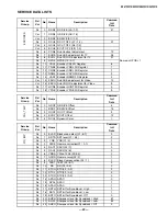
Page 21: ... 21 KV 27FV310 29FV310 32FV310 36FV310 SERVICE DATA LISTS ...
Page 22: ... 22 KV 27FV310 29FV310 32FV310 36FV310 SERVICE DATA LISTS ...
Page 23: ... 23 KV 27FV310 29FV310 32FV310 36FV310 SERVICE DATA LISTS ...
Page 24: ... 24 KV 27FV310 29FV310 32FV310 36FV310 SERVICE DATA LISTS ...
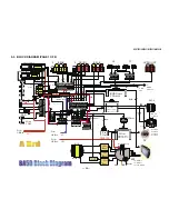
Page 30: ... 30 KV 27FV310 29FV310 32FV310 36FV310 5 3 BLOCK DIAGRAM PAGE 1 OF 4 ...
Page 31: ... 31 KV 27FV310 29FV310 32FV310 36FV310 BLOCK DIAGRAM PAGE 2 OF 4 ...
Page 32: ... 32 KV 27FV310 29FV310 32FV310 36FV310 BLOCK DIAGRAM PAGE 3 OF 4 ...
Page 33: ... 33 KV 27FV310 29FV310 32FV310 36FV310 BLOCK DIAGRAM PAGE 4 OF 4 ...
Page 103: ......
Page 158: ......
Page 159: ......
Page 216: ......
Page 217: ......
Page 266: ......


