Sony JunboTron JME-SA200 Operating Instructions Manual Download Page 54

54

Adjustment

Displaying the Unit Address on the Screen

You can display the numbers set by the address switches located on the
rear of the unit on the screen.

1

Establish communication with the ICU controller (page 21) and
display the MAIN MENU.

2

Press the 

v

 or 

V

 button to select OTHER CONTROL and press the

ENTER button.
The OTHER CONTROL menu appears.


S W I T C H E R   C O N T R O L 
S I G N A L   C O N T R O L 
G E O M E T R Y   C O N T R O L 
M O N I T O R   C O N T R O L 
S C R E E N   C O N T R O L 
S C R E E N   U N I T   C O N T R O L 

O T H E R   C O N T R O L 

* * * * * *   M A I N   M E N U   * * * * * *


    S C R E E N   I N F O 

    P R O D U C T   I N F O 

    P R O C E S S O R   R E G I S T 

    P R O C E S S O R   S E L E C T

* * * *   O T H E R   C O N T R O L   * * * *

3

Press the 

v

 or 

V

 button to select SCREEN INFO and press the ENTER

button.
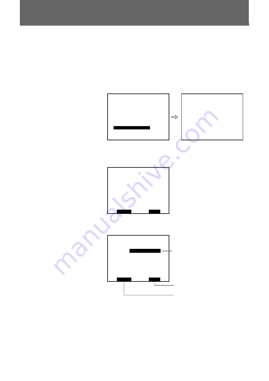
The SCREEN INFO menu appears.


S C R E E N : C U T   O F F 

* * * * *   S C R E E N   I N F O


* * * * *

S T A R T

F 2

F 4

S T O P

4

Press the 

B

 or 

b

 button to select ADDRESS (ID) or ADDRESS (S.

No.)


S C R E E N :

A D D R E S S ( I D )

S T A R T

F 2

F 4

S T O P

* * * * *   S C R E E N   I N F O


* * * * *

5

Press the F2 button.
The selected address is displayed on the screen.

Example of ADDRESS (ID):

  01 (lower two digits of the address

switch setting)

Example of ADDRESS (S. No.):


 S1 (highest one digit of the address

switch setting with prefix S (screen)).

To stop displaying the address

Press the F4 button.

ADDRESS (ID): to display the unit

address (lower two digits of the
address switch setting)

ADDRESS (S. No.): to display the screen

address (highest one digit of the
address switch setting)

to stop displaying the address

to display the address

Summary of Contents for JunboTron JME-SA200

Page 1: ...on Screen Alignment Controller 3 864 808 13 1 Operating Instructions Before operating the unit please read this manual thoroughly and retain it for future reference 1998 by Sony Corporation JME SA200 Ver 02 50 ...

Page 2: ...manual may cause harmful interference to radio communications Operation of this equipment in a residential area is likely to cause harmful interference in which case the user will be required to correct the interference at his own expense Owner s Record The model and serial numbers are located on the rear Record the serial number in the space provided below Refer to these numbers whenever you call...

Page 3: ...ck 11 Detaching the battery pack 12 Connections 13 JumboTron system configuration 13 Connections for using as wireless controller 14 Connections for using as wired controller 16 Registering the Phone Number for the Modem 17 Attaching the Shoulder Strap 19 Before Adjustment Preparing the System 20 Communicating with the ICU Controller 21 When the unit is used as wireless controller 21 When the unit...

Page 4: ... 35 Adjusting the mix level 35 Checking the Screen Display Unit 37 Adjusting the Luminance of a Specified Unit or Cell 39 Resetting the Luminance of a Unit to the Factory Data 44 Registering and Recalling the Unit Cell Numbers 46 Registering the unit cell number 46 Recalling the registered unit or cell 48 Adjusting the Monitor 50 Adjusting the position and boundary of the image on the monitor 50 S...

Page 5: ...s manual explains how to use the JTC P200 and JTC C200 only briefly please refer to the Operating Instructions of the JTC C200 for details Precautions On safety Do not use the unit at extremely high or low temperatures Do not use the unit in high humidity If any abnormality occurs turn off the power and consult with qualified Sony service personnel On cleaning Clean the case and front panel with a...

Page 6: ...rdless of whether it is day or night indoors or outdoors Images to be displayed on the JumboTron screen The JumboTron system can display the following three types of images a Video images input from equipment such as a VCR video camera and video disc INPUT 1 b Computer graphics INPUT 2 c Mixed images of INPUT 1 and INPUT 2 INPUT 1 images are superimposed on the monochrome area of the INPUT 2 image...

Page 7: ...rizontally to suit various uses or locations An example structure of each series is as follows LDU 15 series Picture element pitch 4 dots 4 dots RGB trio dot G B R Cell Unit JumboTron screen 4 cells 16 dots 4 cells 16 dots NTSC max 30 units 120 cells 480 dots PAL max 36 units 144 cells 576 dots NTSC max 40 units 160 cells 640 dots PAL max 48 units 192 cells 768 dots LDU 30 series NTSC max 30 units...

Page 8: ...r Video camera AV switcher Microphone Audio amplifier Speaker system Frame synchronizer Screen site Computer JTC C200 ICU controller Monitor Modem JME UA200 unit alignment controller JumboTron screen JTA LS200 ABC sensor unit JTC P200 image control unit ICU Power source JME SA200 screen alignment controller Cellular phone Public telephone line Digital data card Audio mixer Monitor Overview of the ...

Page 9: ...splay unit Adjusting the luminance of a specified unit or cell The JumboTron screen may partially degrade the brightness or color uniformity after long use The JME SA200 can correct the uniformity by adjusting the luminance or color temperature of a specified unit or cell Adjusting the position and size of the image The JME SA200 can shift the image on the screen vertically or horizontally and cha...

Page 10: ...w or change the set values 7 ENTER button Confirms the selected item and stores the set value 6 CONTROL connector D sub 15 pin Connect to the CONTROL 2 connector of the JTC C200 ICU controller for wired control Front panel Rear panel 1 2 3 4 5 6 7 8 9 º 9 LCD DISPLAY switch Turns on off the backlight of the LCD display window The battery life will be longer if the backlight is turned off 0 Connect...

Page 11: ...If the battery pack is not locked it may fall during operation and the adjustment data may be lost Battery charging time When charging the exhausted battery pack using the AC V615 AC power adaptor the following charging time is required Normal charging time Approx 3 hours 30 minutes Full charging time Approx 4 hours 30 minutes The normal charging time is the time until the charging lamp on the AC ...

Page 12: ...Overview Detaching the battery pack While pressing the BATT EJECT lever downward slide the battery pack in the direction of the arrow and lift it Power Source BATT EJECT lever Power Source and Connections ...

Page 13: ...ublic telephone line EXTERNAL CONTROL to power distribution panel to 100 240 V AC AC IN JTC C200 ICU controller COM 1 Computer Video camera VCR etc Computer AV switcher Interface board JumboTron screen Unit 1 Unit 2 47 Unit 48 JTA LS200 ABC sensor unit IN OUT IN CONTROL 2 or 3 CONTROL 1 LS EXTERNAL CONTROL AC IN JTC P200 ICU to 100 240 V AC to equipment to be controlled with the JTC C200 such as p...

Page 14: ...Connecting diagram Power Source and Connections Connections Digital data card JME SA200 Cellular phone Public telephone line Modem JTC C200 ICU controller COM 2 Inserting the digital data card Prepare a cellular phone digital data card and connecting cable not supplied For usable equipment consult with your Sony distributor 1 Press the EJECT button using the supplied eject tool and remove the dumm...

Page 15: ... Number for the Modem on page 17 Storing the eject tool You can tie the eject tool to the shoulder strap attachment as illustrated Removing the digital data card 1 Press the EJECT button using the supplied eject tool and remove the digital data card 2 Insert the dummy card into the slot When the unit is not used as a wireless controller Be sure to insert the dummy card into the PC CARD slot to pre...

Page 16: ...r by connecting to the JTC C200 ICU controller The connecting cable can be extended up to 1 000 m Connecting diagram Note Use a connector whose size is smaller than the connector guard Power Source and Connections Connections CONTROL JME SA200 D sub 15 pin D sub 15 pin CONTROL 2 JTC C200 ICU controller ...

Page 17: ...he phone number registration is completed 2 Set the POWER switch of the unit ON The title display appears in the display window after about 9 seconds M A I N T E N A N C E E Q U I P M E N T J U M B O T R O N J M E S A 2 0 0 Note When the POWER switch is set to ON the title display will appear in the display window after about 9 seconds 3 Hold down the B button until the PHONE NUMBER display appear...

Page 18: ... N E N U M B E R P H O N E N U M B E R 0 3 1 2 3 4 5 6 7 8 1 2 3 4 5 5 When the phone number input is completed press the ENTER button The phone number is stored in memory and the PHONE NUMBER display disappears Note Do not press the MENU button before pressing the ENTER button in step 5 If you do the PHONE NUMBER display disappears but the input phone number is not stored in the memory Changing t...

Page 19: ...ulder Strap Attach the supplied shoulder strap to the shoulder strap attachments and adjust its length You can use either of the two sets of the shoulder strap attachments at the top or bottom of the unit Power Source and Connections ...

Page 20: ...ends the images such as VCRs and computers 3 Press the I side of the POWER switch on the ICU 4 Press the I side of the POWER switch on the ICU controller to turn on the power of the ICU controller 5 Hold down the ICU button on the ICU controller for more than a second to turn on the power of the ICU 6 Hold down the SCREEN button on the ICU controller for more than a second to turn on the power of ...

Page 21: ...age 17 1 Turn on the power of the cellular phone 2 Set the POWER switch on the unit to ON The title display appears in the display window after about 9 seconds and the unit automatically starts dialing M A I N T E N A N C E E Q U I P M E N T J U M B O T R O N J M E S A 2 0 0 When communication is established the MAIN MENU appears in the display window S W I T C H E R C O N T R O L S I G N A L C O ...

Page 22: ... ON The title display appears in the display window after about 9 seconds M A I N T E N A N C E E Q U I P M E N T J U M B O T R O N J M E S A 2 0 0 When communication is established the MAIN MENU appears in the display window S W I T C H E R C O N T R O L S I G N A L C O N T R O L G E O M E T R Y C O N T R O L M O N I T O R C O N T R O L S C R E E N C O N T R O L S C R E E N U N I T C O N T R O L ...

Page 23: ...R C O N T R O L S I G N A L C O N T R O L G E O M E T R Y C O N T R O L M O N I T O R C O N T R O L S C R E E N C O N T R O L S C R E E N U N I T C O N T R O L O T H E R C O N T R O L M A I N M E N U S C R E E N I N F O P R O D U C T I N F O P R O C E S S O R R E G I S T P R O C E S S O R S E L E C T O T H E R C O N T R O L 3 Press the v or V button to select PROCESSOR REGIST and press the ENTER b...

Page 24: ...rth ICU 6 After setting press the ENTER button The selected ID number is registered and REGISTERED appears Notes The PROCESSOR No 1 setting is fixed Make sure that the ID number to be registered on this unit is the same as that registered on the ICU For details refer to the Operating Instructions supplied with the JTC C200 ICU controller Do not set the same ID number for two or more ICUs If you sp...

Page 25: ...C R E E N C O N T R O L S C R E E N U N I T C O N T R O L O T H E R C O N T R O L M A I N M E N U S C R E E N I N F O P R O D U C T I N F O P R O C E S S O R R E G I S T P R O C E S S O R S E L E C T O T H E R C O N T R O L 3 Press the v or V button to select PROCESSOR SELECT and press the ENTER button The PROCESSOR SELECT menu appears P R O C E S S O R N o 1 P R O C E S S O R N o 2 P R O C E S S ...

Page 26: ...M I X L E V E L R E D M A X 4 0 M I N 0 G R N M A X 4 0 M I N 0 B L U M A X 4 0 M I N 0 3 Set the number of display units constituting the screen Press the vor V button to select X Y or Z and press the B or bbutton to change the number By pressing the vbutton X Y and Z are selected in order By pressing the V button they are selected in the reverse order S C R E E N C O N T R O L U N I T T Y P E L ...

Page 27: ...stment 27 To return to the MAIN MENU Press the MENU button Note Do not press the MENU button before pressing the ENTER button in step 4 If you do the set data are not stored in the memory Before Adjustment ...

Page 28: ...O L O T H E R C O N T R O L M A I N M E N U S W I T C H E R C O N T R O L M A S T E R I N P U T 1 I N P U T 1 C O M P O S I T E 3 Select the screen display mode Press the vor V button to select MASTER and press the B or bbutton to select the display mode S W I T C H E R C O N T R O L M A S T E R I N P U T 1 I N P U T 1 C O M P O S I T E 4 When INPUT 1 is selected for MASTER select the type of the ...

Page 29: ... A I N M E N U H S H I F T 0 V S H I F T 0 H Z O O M 1 0 0 V Z O O M 1 0 0 A S P E C T R A T I O 1 3 3 M E M O R Y N U M B E R 0 G E O M E T R Y C O N T R O L 3 Adjust the position and size of the image on the screen Press the vor V button to select the adjustment item and press the B or bbutton to change the value H S H I F T 0 V S H I F T 0 H Z O O M 1 0 0 V Z O O M 1 0 0 A S P E C T R A T I O 1...

Page 30: ... in step 4 If you do the adjusted data are not stored in the memory Displaying the aspect ratio When you change the image size with H ZOOM and V ZOOM the aspect ratio of the adjusted image is calculated and displayed on ASPECT RATIO Example Aspect ratio is 1 33 when the image size is 4 3 Aspect ratio is 1 78 when the image size is 16 9 H S H I F T 0 V S H I F T 0 H Z O O M 1 0 0 V Z O O M 1 0 0 A ...

Page 31: ... E E N U N I T C O N T R O L O T H E R C O N T R O L M A I N M E N U S I G N A L C O N T R O L I N P U T 1 I N P U T 2 3 Press the vor V button to select the input INPUT 1 or INPUT 2 and press ENTER button The SIG CTRL menu appears S I G C T R L I N P U T 1 C O L O R 3 2 H U E 3 2 S H A R P N E S S 7 G E O M E T R Y M E M N O 1 M O N I T O R M E M N O 1 f H 1 5 7 5 K H z f V 6 0 0 0 H z S I G T Y ...

Page 32: ...he SIGNAL CONTROL menu appears S W I T C H E R C O N T R O L S I G N A L C O N T R O L G E O M E T R Y C O N T R O L M O N I T O R C O N T R O L S C R E E N C O N T R O L S C R E E N U N I T C O N T R O L O T H E R C O N T R O L M A I N M E N U S I G N A L C O N T R O L I N P U T 1 I N P U T 2 3 Press the vor V button to select the input INPUT 1 or INPUT 2 and press ENTER button The SIG CTRL menu ...

Page 33: ...ty Adjustable range is 0 63 HUE Adjusts the color tint Pressing the b button makes the picture greener pressing the B button makes the picture purpler Adjustable range is 0 63 SHARPNESS Adjusts the sharpness Pressing the b button makes the picture sharper pressing the B button makes the picture softer Adjustable range is 0 15 2 After adjusting press the ENTER button The adjusted data are stored in...

Page 34: ...D U 1 5 N U M B E R O F U N I T X 4 0 Y 3 0 Z 1 B R I G H T N E S S 1 5 M I X L E V E L R E D M A X 4 0 M I N 0 G R N M A X 4 0 M I N 0 B L U M A X 4 0 M I N 0 3 Press the vor V button to select BRIGHTNESS and press the B or b button to adjust the brightness level The brightness level is adjustable in a range of 1 16 The higher the level is the brighter the screen becomes S C R E E N C O N T R O L...

Page 35: ... N P U T 1 2 I N P U T 1 C O M P O S I T E 3 Display the MAIN MENU press the vor V button to select SCREEN CONTROL and press the ENTER button The SCREEN CONTROL menu appears M A I N M E N U S W I T C H E R C O N T R O L S I G N A L C O N T R O L G E O M E T R Y C O N T R O L M O N I T O R C O N T R O L S C R E E N C O N T R O L S C R E E N U N I T C O N T R O L O T H E R C O N T R O L S C R E E N ...

Page 36: ...ble range for each item is 0 255 S C R E E N C O N T R O L U N I T T Y P E L D U 1 5 N U M B E R O F U N I T X 4 0 Y 3 0 Z 1 B R I G H T N E S S 1 5 M I X L E V E L R E D M A X 4 0 M I N 0 G R N M A X 4 0 M I N 0 B L U M A X 4 0 M I N 0 5 Press the ENTER button The adjusted data are stored in memory To return to the MAIN MENU Press the MENU button Note Do not press the MENU button before pressing ...

Page 37: ...T R O L S C R E E N U N I T C O N T R O L O T H E R C O N T R O L M A I N M E N U S C R E E N U N I T C O N T R O L C H E C K A D J U S T R E G I S T R E C A L L F A C T O R Y D A T A 3 Press the vor V button to select CHECK and press the ENTER button The SCREEN UNIT CHECK menu appears S C R E E N U N I T C H E C K M O D E T E S T U N I T N U M B E R X 1 Y 1 S C R E E N N U M B E R 1 4 If two or m...

Page 38: ...ssigned unit The stair step and color bars change automatically on the unit Check if the unit is operating properly Test pattern Operating and circuit to be checked Stair step data of the same bit Bit errors etc Color bars Data latch timing etc To stop the test pattern display Press the MENU button The display window returns to the MAIN MENU Counting the unit number The top left unit on the screen...

Page 39: ... C R E E N U N I T C O N T R O L O T H E R C O N T R O L M A I N M E N U S C R E E N U N I T C O N T R O L C H E C K A D J U S T R E G I S T R E C A L L F A C T O R Y D A T A 3 Press the vor V button to select ADJUST and press the ENTER button The SCREEN UNIT ADJUST menu appears S C R E E N U N I T A D J U S T U N I T T Y P E L D U 1 5 A D J U S T I d r v R G B B A C K G R O U N D W H I T E 4 Sele...

Page 40: ...X or vertical Y direction S C R E E N U N I T A D J U S T B A C K G R O U N D W H I T E C O N T R A S T 1 2 8 UNIT X 4 Y 3 Z 1 BLOCK X Y CELL X Y I d r v B L U E I d r v R E D I d r v G R E E N 8 Press the ENTER button The cursor moves to BLOCK X for the screen using the LDU 30 series units and to CELL X for the screen using the units other than the LDU 30 series For the screen using the units oth...

Page 41: ...hing 13Adjust the luminance Press the B or bbutton to adjust the luminance by observing the screen The currently stored luminance level is displayed as 0 Press the bbutton to increase the luminance and the B button to decrease it When WHITE is selected for the adjustment color pressing the B or b button changes the data of three colors simultaneously When the specified color is selected pressing t...

Page 42: ...nment step 9 To adjust another unit repeat from the unit number assignment step 7 To adjust another item Press the MENU button once to return to the SCREEN UNIT ADJUST menu Press the vor V button to select ADJUST and repeat from selecting the adjustment item and adjustment color step 4 To clear all the input unit block and cell numbers press the MENU button on the SCREEN UNIT ADJUST menu and repea...

Page 43: ...tical direction 0 to 4 1 to the number of units in vertical direction 0 to 2 0 to 4 X 1 Y 1 X 2 Y 1 X 3 Y 1 X 4 Y 1 X 1 Y 2 X 2 Y 2 X 3 Y 2 X 4 Y 2 X Y X 1 Y 1 X 2 Y 1 X 1 Y 1 X 2 Y 1 X 1 Y 1 X 2 Y 1 X 1 Y 1 X 2 Y 1 X 1 Y 2 X 2 Y 2 X 1 Y 2 X 2 Y 2 X 1 Y 2 X 2 Y 2 X 1 Y 2 X 2 Y 2 X 1 Y 3 X 2 Y 3 X 1 Y 3 X 2 Y 3 X 1 Y 3 X 2 Y 3 X 1 Y 3 X 2 Y 3 X 1 Y 4 X 2 Y 4 X 1 Y 4 X 2 Y 4 X 1 Y 4 X 2 Y 4 X 1 Y 4 ...

Page 44: ... T C O N T R O L O T H E R C O N T R O L M A I N M E N U S C R E E N U N I T C O N T R O L C H E C K A D J U S T R E G I S T R E C A L L F A C T O R Y D A T A 3 Press the v or V button to select FACTORY DATA and press the ENTER button The SCREEN UNIT F DATA menu appears and UNIT X 1 Y 1 of screen number 1 flash S C R E E N U N I T F D A T A B A C K G R O U N D W H I T E F I X E D U N I T X 1 Y 1 Z...

Page 45: ...recall the factory data on another unit After saving the factory data or pressing the F4 button the previously selected unit flashes To recall the factory data on another unit repeat from the unit number assignment step 4 To clear the assigned unit number press the MENU button and repeat from step 3 Notes Once you have reset the luminance of a specified unit to the factory data you can no longer r...

Page 46: ...I T C O N T R O L C H E C K A D J U S T R E G I S T R E C A L L F A C T O R Y D A T A 3 Press the v or V button to select REGIST and press the ENTER button The SCREEN UNIT REGIST menu appears S C R E E N U N I T R E G I S T M O D E W H I T E C O N T R A S T 1 5 U N I T N U M B E R C E L L N o X Y Z P X P Y 1 1 1 0 0 4 Press the v or V button to select MODE and press the B or b button to select the...

Page 47: ...rizontal X or vertical Y direction S C R E E N U N I T R E G I S T M O D E W H I T E C O N T R A S T 1 5 U N I T N U M B E R C E L L N o X Y Z P X P Y 1 1 1 0 0 For counting the cell number see page 43 7 Press the ENTER button The specified unit cell number is stored in memory and WRITE COMPLETE appears To register another unit cell number Repeat from the unit cell number assignment step 6 To regi...

Page 48: ...e SCREEN UNIT CONTROL menu appears S C R E E N U N I T C O N T R O L C H E C K A D J U S T R E G I S T R E C A L L F A C T O R Y D A T A 3 Press the v or V button to select RECALL and press the ENTER button The SCREEN UNIT RECALL menu appears The unit cell number stored first in the memory is displayed S C R E E N U N I T R E C A L L M O D E S E L E C T S E L E C T P R E V N E X T U N I T N U M B ...

Page 49: ...returns to the SCREEN UNIT CONTROL menu and the indicator on the rear panel of the unit stops flashing Notes If you press the ENTER button when there is no registered unit cell numbers DATA NOTHING appears If you press the b button when the last registered unit cell number is recalled Read NEXT NO DATA appears If you press the B button when the first registered unit cell number is recalled Read PR...

Page 50: ...6 4 0 V B O U N D A R Y 4 8 0 M E M O R Y N U M B E R 1 M O N I T O R C O N T R O L 3 Adjust the position and boundary of the image on the monitor Press the v or V button to select the adjustment item and press the B or b button to change the value H C E N T E R 8 V C E N T E R 0 H B O U N D A R Y 6 4 0 V B O U N D A R Y 4 8 0 M E M O R Y N U M B E R 1 M O N I T O R C O N T R O L Adjustment item H...

Page 51: ...on The adjusted data are stored to the currently selected memory number To return to the MAIN MENU Press the MENU button Note Do not press the MENU button before pressing the ENTER button in step 4 If you do the adjusted data are not stored in the memory ...

Page 52: ... O N T R O L M A I N M E N U S I G N A L C O N T R O L I N P U T 1 I N P U T 2 3 Press the v or V button to select the input INPUT 1 or INPUT 2 and press ENTER button The SIG CTRL menu appears S I G C T R L I N P U T 1 C O L O R 3 2 H U E 3 2 S H A R P N E S S 7 G E O M E T R Y M E M N O 1 M O N I T O R M E M N O 1 f H 1 5 7 5 K H z f V 6 0 0 0 H z S I G T Y P E N T S C I N P U T 1 C O M P O S I T...

Page 53: ... O N T R O L S C R E E N C O N T R O L S C R E E N U N I T C O N T R O L O T H E R C O N T R O L M A I N M E N U S C R E E N I N F O P R O D U C T I N F O P R O C E S S O R R E G I S T P R O C E S S O R S E L E C T O T H E R C O N T R O L 3 Press the v or V button to select SCREEN INFO and press the ENTER button The SCREEN INFO menu appears S C R E E N C U T O F F S C R E E N I N F O S T A R T F 2...

Page 54: ...E C T O T H E R C O N T R O L 3 Press the v or V button to select SCREEN INFO and press the ENTER button The SCREEN INFO menu appears S C R E E N C U T O F F S C R E E N I N F O S T A R T F 2 F 4 S T O P 4 Press the B or b button to select ADDRESS ID or ADDRESS S No S C R E E N A D D R E S S I D S T A R T F 2 F 4 S T O P S C R E E N I N F O 5 Press the F2 button The selected address is displayed o...

Page 55: ... O N T R O L O T H E R C O N T R O L M A I N M E N U S C R E E N I N F O P R O D U C T I N F O P R O C E S S O R R E G I S T P R O C E S S O R S E L E C T O T H E R C O N T R O L 3 Press the v or V button to select PRODUCT INFO and press ENTER button The information about the software version appears in the display window N a m e S A 2 0 0 V e r s i o n 0 2 5 0 s a 2 0 0 s y s 0 2 0 1 s a 2 0 0 k ...

Page 56: ...the unit Troubleshooting If you think you have a problem during operation check through the following list The title display does not appear after the power has been turned on and 9 seconds or more have elapsed Problem Corrective action Attach the battery pack The battery is exhaused completely Cause Charge the battery The MAIN MENU does not appear in the display window The unit is not connected t...

Page 57: ...000 m 3280 feet max Input output CONTROL D sub 15 pin for RS 422 1 PC CARD PCMCIA type II slot Supplied accessories Dummy card 1 inserted into the unit at the factory Shoulder strap 1 Eject tool 1 Operating Instructions 1 Optional accessories Rechargeable battery pack NP F750 AC power adaptor AC V615 for charging the battery pack Pin assignment CONTROL connector D sub 15 pin Pin No Signal Pin No S...

Page 58: ......

Page 59: ......

Page 60: ...60 Others Sony Corporation Printed in Japan ...

Reviews: