10
Locations and Functions of Parts
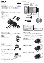
Front left
a
RET 1 (return video 1) button
The return video 1 signal from the camera control unit is
monitored on the viewfinder screen while this button is
pressed. It function the same as the RET 1 buttons on the
handle (
) and that on the operation panel on the rear
of the camera (
).
You can also assign other functions to this button, using the
menu displayed on the viewfinder screen.
b
MIC 1 IN (microphone 1 input) connector (XLR 3-
pin)
Connect a microphone.
This connector and the AUDIO IN CH-1 connector (
) on the operation panel on the rear of the camera are
alternately activated with the CH1 audio input select
switch (
c
MIC (microphone) power switch
+48V:
To supply a power of +48 V to the connected
microphone.
OFF:
Not to supply a power to the connected microphone.
d
SHUTTER switch
This switch does not function.
e
INTERCOM LEVEL control
To adjust the intercom/earphone volume level.
The intercom level adjustment is enabled when the
INTERCOM 1 and 2 LEVEL/MIC switches (on the SY-
type operation panel,
) or the LEVEL switch (on
the European-type operation panel,
) on the rear of
the camera are set to “FRONT.”
f
RET 2 (return video 2) button
When this button is pressed, the picture on the viewfinder
changes to the return video signal selected with the RET 2
select switch (
page 12
) on the operation panel on the
rear of the camera.
You can also assign other functions to this button, using the
menu displayed on the viewfinder screen.
SERIES
d
SHUTTER switch
e
INTERCOM LEVEL control
f
RET 2 button
b
MIC 1 IN connector
a
RET 1 button
c
MIC power switch


