


6-26
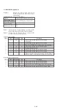
18. Electronic viewfinder system adjustments
(VF-102 board)
Note :
About 2200V dc is applied to CRT anode and about 200
Vdc to the grid. Be careful not to touch them. If hand
touches them, there is danger of electric shock
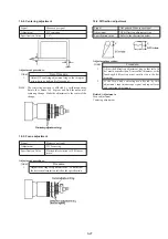
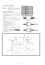
Preparation :
1.
Disconnect a flexible board from CN901 on VF-102 board.
2.
Connect equipments as follows.
Required signals
1.
Monoscope signal
Output amplitude:
1.0 Vp-p (75
Ω
terminated)
Horizontal resolution:
600 TV lines or more
Vertical resolution:
350 TV lines or more
2.
Dot pattern signal
Output amplitude
1.0 Vp-p (75
Ω
terminated)
3.
Contrast signal
Output amplitude
0.5 Vp-p (75
Ω
terminated)
fH :
15.750kHz (NTSC)
15.625kHz (PAL)
fV :
60Hz (NTSC)
50Hz (PAL)
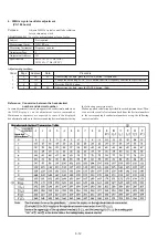
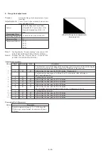
Others: Complies with NTSC and PAL. (Refer to Fig. 6-1-12.)
Fig. 6-1-11
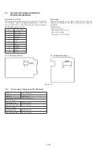
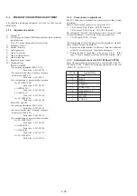
18-1. Power supply voltage check
Measuring Instrument
Digital voltmeter
EVF5V
Measurement Point
CN901 Pin
1
Specification Value
4.65 + 0.1Vdc
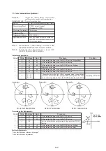
18-2. Horizontal and vertical position
Purpose :
Maintains horizontal position.
Adjustment error :
Horizontal position cannot be maintained.
Signal
Monoscope signal
Adjustment
RV905
Specification Value
Overscan 3.5 ± 3.5%
(horizontal) (one side)
Overscan 4.5 ± 1.5% (vertical)(one side)
Adjustment procedure:
Order
Procedure
1
Confirm that the horizontal and vertical picture sizes
satisfy the specification values.
18-3. BRIGHT adjustment
Signal
Monoscope signal
Measurement Point
CRT screen
Adjustment
RV904
Specification Value
Each step of gray scale signal is
displayed clearly.
Adjustment procedure:
Order
Procedure
1
Adjust RV904 until each step of gray scale signal is
clearly display. (For the brighter region, do not
increase brightness to such an extent that the cross-
hatch at the center of monoscope signal becomes
flared. For the dark region, do not decrease brightness
to such an extent that the first step (the darkest step)
and the third step cannot be identified.)
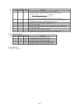
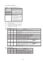
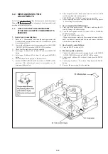
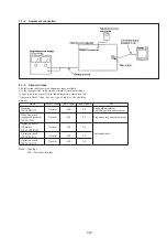
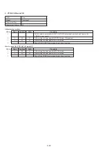
VF-102 BOARD (SIDE A)
Fig 6-1-12
Summary of Contents for Handycam CCD-TR501E
Page 7: ......
Page 8: ......
Page 9: ......
Page 10: ......
Page 11: ......
Page 12: ......
Page 13: ......
Page 14: ......
Page 15: ......
Page 16: ......
Page 17: ......
Page 18: ......
Page 19: ......
Page 20: ......
Page 21: ......
Page 22: ......
Page 23: ......
Page 24: ......
Page 30: ...2 6 2 11 INTERNAL VIEWS LEFT SIDE RIGHT SIDE ...
Page 32: ......
Page 33: ......
Page 34: ......
Page 35: ......
Page 36: ......
Page 37: ......
Page 38: ......
Page 39: ......
Page 40: ......
Page 41: ......
Page 42: ......
Page 43: ......
Page 44: ......
Page 45: ......
Page 46: ......
Page 47: ......
Page 48: ......
Page 49: ......
Page 50: ......
Page 51: ......
Page 52: ......
Page 53: ......
Page 54: ......
Page 55: ......
Page 56: ......
Page 57: ......
Page 58: ......
Page 59: ......
Page 60: ......
Page 61: ......
Page 127: ......
Page 166: ......
Page 168: ......
Page 169: ......
Page 170: ......
Page 171: ......
Page 172: ......
Page 173: ......
Page 174: ......
Page 175: ......
Page 176: ......
Page 177: ......
Page 178: ......
Page 179: ......
Page 180: ......
Page 181: ......
Page 182: ......
Page 183: ......
Page 184: ......
Page 185: ......
Page 186: ......
Page 187: ......
Page 188: ......
Page 189: ......
Page 190: ......
Page 191: ......
Page 192: ......
Page 193: ......
Page 194: ......
Page 195: ......
Page 196: ......
Page 197: ......
Page 198: ......
Page 199: ......
Page 200: ......
Page 201: ......
Page 202: ......
Page 203: ......