2-3
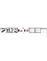
2-5. FDD BLOCK ASSEMBLY
2-6. PK-59 BOARD, LCD MODULE
[SERVICE POSITION (LCD PANEL AND PK-59 BOARD)]
Note: When installing PK-59 board, connect RV701 with
zoom knob and S708 with PLAY/CAMERA knob.
2
FDD block assembly
4
Flexible board
(CN602)
1
Open the side
Cabinet.
3
Flexible board
(CN601)
2
Two screws
7
Two screws
6
Four screws
3
Two screws
8
screw
1
Flexible board
(CN851)
5
Flexible board
(CN901)
4
Cold cathode
fluorescent tube
9
PK-59 board
0
LCD module
RV701
Zoom knob
S708
PLAY/CAMERA knob
Adjustment remote
commander
CPC-9 jig
(J-6082-393-C)
(Note 1)
FC-86 board
LCD panel
Note 1: Don’t use the 12 pin flexible board of CPC-9 jig.
It causes damage to the unit.
Note 2: Connection method refer to page 6.
Stand
AC IN
AC power
adaptor
Cabinet (front)
block assembly
: Contacting surface
Extension cable (16P)
(J-6082-427-A)
FDD block
assembly
Lens block assembly
Extension cable
(J-6082-427-A)
(Note 2)
PK-59 board
Summary of Contents for FD Mavica MVC-FD75
Page 8: ...1 1 SECTION 1 GENERAL MVC FD75 This section is extracted from instruction manual ...
Page 9: ...1 2 ...
Page 10: ...1 3 ...
Page 11: ...1 4 ...
Page 12: ...1 5 ...
Page 13: ...1 6 ...
Page 14: ...1 7 ...
Page 15: ...1 8 ...
Page 16: ...1 9 ...
Page 17: ...1 10 1 10 E ...


