background image

1-24

DXC-D35/D35WS(UC)

DXC-D35P/D35WSP(CE) V1

46

Chapter 3

Shooting

Chapter 3  Shooting

Shooting with the DSR-1/1P

The DXC-D35/D35P/D35WS/D35WSP docks with
the DSR-1/1P to configure a DVCAM Camcorder.
The following describes how to shoot using a
DVCAM camcorder.

Using the ClipLink Function

The ClipLink function can be used at all stages from
shooting to editing.  This function makes editing
operations more efficient by automatically recording
index pictures (Mark IN point images) that provide a
searchable index of recorded scenes, along with other
data such as time code and scene numbers.

For concept of the ClipLink function, see the section “What
Is ClipLink”(page 102).

1

Dock the DSR-1/1P to the camera head and turn on
the power, then perform steps 

2

 to 

10

 from “Basic

Procedure for Shooting” (page 43).

2

Insert a cassette into the DSR-1/1P and set
ClipLink mode to ON by menu setting.

For details of this operation, see the operating
instructions for the DSR-1/1P.

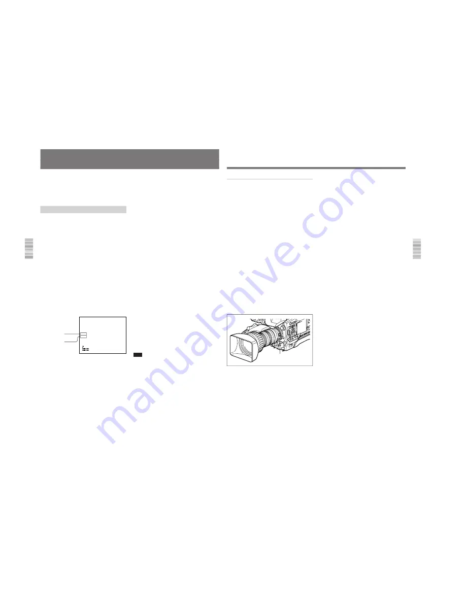
The following display appears on the viewfinder
screen.

    TCG 12:34:56:00

                       W:A

CLIPM

198                   F5.6

                      56ND

             99 04 01

             10:10    AM

a)

For details, see “Basic menu page 6” (page 60).

To record the cassette name/number
Access basic menu page 6 to specify a name or
number for the inserted cassette.

For details, see “Basic menu  page 6” (page 60).

ClipLink mode indication:
CLIP M or C

a)

Clip remaining:
Indicates the number of
available Index pictures
(198 max.)

3

Press the VTR button on the camera head or the
lens.

The DSR-1/1P starts recording, and the REC/
TALLY indicator lights in the viewfinder.
Meanwhile, the time code at the recording start
point (Rec IN) is recorded (HH:MM:SS) in the
DSR-1/1P’s internal memory.

4

When a shooting of the scene completes, press the
VTR button on the camera head or the lens.

This pauses recording.
To continue recording the next scene, repeat steps

3

 and 

4

.  The scene number will be automatically

incremented.

To set/clear NG (No Good)
If you press the NG button before you start
shooting the next scene, the previous scene will be
designated as “NG” (the “NG” display appears in
the viewfinder).
Once NG has been set, you can cancel it by
pressing the NG button again before you start
shooting the next scene (the “NG” display in the
viewfinder disappears, which means that the
previous scene has been re-designated as “OK”).
Each time you press the NG button before starting
shooting the next scene, the status of the previous
scene toggles between “NG” and “OK”.  It is
always the last selected status that will take effect
and be stored in the cassette memory.

5

To finish recording, press the STOP button on the
DSR-1/1P.

This stops recording.

Note

When using the ClipLink function while shooting, if
you continue shooting after stopping or if you change
the tape’s recording position, your subsequent shots
may overwrite and erase the previously recorded
ClipLink log data (time codes, scene number, etc.) or
index pictures.
To avoid this problem, press the DSR-1/1P’s ClipLink
CONTINUE button before restart of shooting.

For details, see the operating instructions for the DSR-1/1P.

Chapter 3  Shooting

47

Chapter 3  Shooting

Setting Mark IN/OUT points as you shoot

Instead of continuing shots from scene to scene, you
can specify Mark IN and Mark OUT points as you
shoot and set scene numbers (ranging from 001 to
198).

1

Perform steps 

1

 and 

2

 from “Using the ClipLink

Function” (page 46).

2

Access basic menu page 6 and perform the
following operations.
1) Set MARK/CUE to MARK.

The ClipLink mode indication “CLIP M”
appears on the viewfinder screen.

2) Set the cassette name or number if necessary.

For details of menu operations, see “Basic Menu
Operations” (page 58).

3

Press the VTR button on the camera head or the
lens.

The DSR-1/1P starts recording, and the REC/
TALLY indicator(s) light(s) in the viewfinder.

4

Press the TAKE button when you find a shot
where you would like to set a Mark IN point.

The TAKE/TALLY indicator (orange) lights in the
viewfinder and “TAKE” appears on the screen.

5

Press the TAKE button when you find a shot
where you would like to set a Mark OUT point.

The TAKE/TALLY indicator (orange) goes out in
the viewfinder and the “TAKE” disappears from
the screen.
At this time, the time code (HH:MM:SS) at the
Mark IN/OUT point for scene 001 is recorded to
the DSR-1/1P’s internal memory, and then
recorded to the cassette memory.

To set/clear NG
If you press the NG button before you set the next
Mark IN point, the previous scene will be
designated as “NG” (the “NG” display appears in
the viewfinder).
Once NG has been set, you can cancel it by
pressing the NG button again before you set the
next Mark IN point (the “NG” display in the
viewfinder disappears).

6

Repeat steps 

4

 and 

5

 as needed to record (to

cassette memory) time codes at Mark IN/OUT
points, scene numbers, and NG designations to the
cassette memory.

The scene number is automatically incremented
each time you specify a Mark OUT point.

7

To finish shooting, press the VTR button on the
camera head or the lens, then press the DSR-1/1P’s
STOP button.

This stops the recording operation.
The index pictures of each Mark IN point are
recorded onto the tape.

TAKE button

Summary of Contents for DXC-D35

Page 1: ...COLOR VIDEO CAMERA DXC D35 DXC D35P DXC D35WS DXC D35WSP SERVICE MANUAL Volume 1 1st Edition WS ...

Page 2: ...l ausgeführt werden Um die Gefahr eines elektrischen Schlages Feuergefahr und Verletzungen zu vermeiden sind bei Wartungsarbeiten strikt die Angaben in der Anleitung zu befolgen Andere als die angegeben Wartungsarbeiten dürfen nur von Personen ausgeführt werden die eine spezielle Befähigung dazu besitzen AVERTISSEMENT Ce manual est destiné uniquement aux personnes compétentes en charge de l entret...

Page 3: ...t recommandé par le constructeur Mettre au rebut les batteries usagées conformément aux instructions du fabricant ADVARSEL Lithiumbatteri Eksplosjonsfare Ved utskifting benyttes kun batteri som anbefalt av apparatfabrikanten Brukt batteri returneres apparatleverandøren VARNING Explosionsfara vid felaktigt batteribyte Använd samma batterityp eller en likvärdig typ som rekommenderas av apparattillve...

Page 4: ...United States and Canada only Caution Do not handle damaged or leaking nickel cadmium batteries For the customers in the Netherlands Voor de klanten in Nederland Dit apparaat bevat een MnO2 Li en Li ion batterij voor memory back up Raadpleeg uw leverancier over de verwijdering van de batterij op het moment dat u het apparaat bij einde levensduur afdankt Gooi de batterij niet weg maar lever hem in ...

Page 5: ...ent of CCD Unit 2 5 2 4 Connectores and Cables 2 7 2 4 1 Connector Input Output Signals 2 7 2 4 2 Connection Connector 2 11 2 5 How to Attach of the Extension Board EX 591 2 11 2 6 Replacement Way of ROM IC102 2 12 2 7 Switch Settings on Boards 2 12 2 8 DC DC Converter Voltage 2 13 2 9 Recommended Replacement Parts 2 14 2 10 Attaching the 4 type or 5 type Viewfinder 2 15 2 11 Disconnecting Connect...

Page 6: ...justment 3 9 3 3 7 Y VBS Level Adjustment 3 10 3 3 8 Y YC Level Adjustment 3 10 3 3 9 Chroma YC Level Adjustment 3 11 3 3 10 VF SYNC BLKG Level Adjustment 3 11 3 3 11 CCD Output Level Adjustment 3 12 3 3 12 Carrier Adjustment at DPR Double Pixel Reading ON 3 13 3 3 13 Shading Adjustment 3 13 3 3 14 Flare Adjustment 3 14 3 3 15 MIC Level MIC Level IND Adjustment 3 15 3 3 16 Character Position Adjus...

Page 7: ...ents block diagrams schematic diagrams and board layouts of the viewfinder For obtaining contact your local Sony Sales Office Service Center Service Manual VCT U14 Available on request Part No 9 977 221 01 This manual describes exploded view and parts list of the tripod adaptor For obtaining contact your local Sony Sales Office Service Center Service Manual VCL 918BY Available on request Part No 9...

Page 8: ......

Page 9: ...ction is extracted from operation manual 2000 by Sony Corporation Operating Instructions Before operating the unit please read this manual thoroughly and retain it for future reference 3 203 895 11 1 ColorVideo Camera WS DXC D35K D35PK DXC D35L D35PL DXC D35WSL D35WSPL DXC D35H D35PH ...

Page 10: ... magnitude to constitute a risk of electric shock to persons This symbol is intended to alert the user to the presence of important operating and maintenance servicing instructions in the literature accompanying the appliance Owner s Record The model and serial numbers are located on the top Record these numbers in the spaces provided below Refer to them whenever you call upon your Sony dealer reg...

Page 11: ...upply 40 Using Battery Packs 40 Camera Adaptor Power Supply 41 Table of Contents 5 Chapter 4 Viewfinder Screen Indications and Menus Table of Contents Basic Procedure for Shooting 43 Using the DynaLatitude Function 45 Shooting with the DSR 1 1P 46 Using the ClipLink Function 46 Using the Edit Search Function While Back Space Editing 48 Using the Freeze Mix Function 49 Viewfinder Screen Indications...

Page 12: ...vity 91 Macrophotography 91 Settings for Special Cases 92 Skin Detail Correction 93 Adjusting Color in the Specified Area 93 Important Notes on Operation 95 Characteristics of CCD Sensors 96 Warning Indications 97 Specifications 98 Related Products 99 Chart of Optional Components and Accessories 101 What Is ClipLink 102 How ClipLink Changes Video Production Techniques 102 ClipLink Operation Flow 1...

Page 13: ...djustment of contrast control in each pixel in accordance with a histogram of luminance signal levels see page 45 DCC dynamic contrast control plus Prevents white breakup when shooting a high intensity subject and also prevents color faults in high intensity subject Black stretch and compress Enables control of luminance signal levels in black areas without changing the hue Variety of detail corre...

Page 14: ...time for all cuts Total recording time for current cut Viewfinder super detail Video signals for the viewfinder are mixed with DTL signals to make focusing easier Features Chapter 1 Overview Chapter 1 Overview 11 Dual zebra pattern display Two types of zebra patterns zebra 1 and zebra 2 can be displayed simultaneously or independently The zebra 1 can be set to the levels ranging from 70 to 90 IRE ...

Page 15: ...the safety zone size through menu setting see page 65 1 ID signals complying with EIAJ CPR 1204 DXC D35WSL or complying with ETS WSS DXC D35WSPL 2 Video signals refer to the following Video signals output from the VIDEO OUT connector and MONITOR OUT connector The Y component of Y C separate signals and the Y component of component signals output from the VTR connector Features Chapter 1 Overview C...

Page 16: ... Locked position Pull the upper panel forward and then lift it up Location and Function of Parts Chapter 1 Overview Chapter 1 Overview 15 CAM DL This setting uses the DynaLatitude function which finely adjusts the contrast of each pixel according to a histogram of luminance signal levels Access advanced menu page 2 to set the DynaLatitude function ON or OFF The DynaLatitude effect can be set to an...

Page 17: ...iate to the lighting conditions See page 43 5 Lens mount Attach the zoom lens here Illustration DXC D35WS D35WSP Chapter 1 Overview Chapter 1 Overview 17 6 SHUTTER switch Use this switch to set the shutter speed CLS clear scan or EVS setting see page 84 Usually set this switch to OFF 7 TAKE button Press this button to specify an editing point Mark IN OUT or cue point at the current tape position d...

Page 18: ... RM M7G to the camera control unit EZ mode cannot be used if the RM M7G is connected to the camera head Location and Function of Parts qa LENS connector 12 pin for 2 3 inch lens Connect the lens connector qs VF viewfinder connector 8 pin This is the connector for the DXF 41 51 viewfinder Note When using this connector do not connect a DXF 801 801CE viewfinder to the VF connector on the front of th...

Page 19: ... this button connects the return video signal from the camera control unit to the viewfinder Starting and stopping recording is controlled on the VTR qs Instant automatic iris adjustment button While using manual iris control press this button to switch temporarily to the automatic iris control setting The automatic setting is maintained as long as you hold the button down qd IRIS selector This se...

Page 20: ...IGHT brightness control This adjusts the brightness of the viewfinder image See page 88 qd Eyepiece release catch To view the viewfinder screen directly press this catch and hinge up the eyepiece qf TALLY switch Set this switch to the ON position to use the tally lamp qa qg DISPLAY switch Set this switch to OFF when you want to remove the character data from the viewfinder and the monitor connecte...

Page 21: ...cover Replacing the Lithium Battery Chapter 2 Fitting and Connections Chapter 2 Fitting and Connections 25 Fitting a VTR 1 Set the PRO 76 pin DIGITAL connector on the DSR 1 1P The camera connector on the PVV 3 3P is PRO 50 pin For details see the operating instructions for the DSR 1 1P 2 Loosen the two screws and remove the shoulder pad 3 Align the projection on the bottom of the DSR 1 1P with the...

Page 22: ...s 27 Using the Camcorder Grip When using the camera head with a VTR as a camcorder you can replace the camera head s grip with a camcorder grip not supplied The type of camcorder grip and the method for attaching it differ slightly depending on the type of VTR Attaching a camcorder grip to the DSR 1 1P 1If the viewfinder is attached adjust the viewfinder to the full forward position For details se...

Page 23: ...he grip for the DVCAM camcorder Grip for the DVCAM camcorder Connection plate Attaching a camcorder grip to the PVV 3 3P 1 Perform steps 2 to 4 in Fitting a VTR 2 If the viewfinder is attached adjust the viewfinder to the full forward position For details see Adjusting the viewfinder position on page 32 Fitting a VTR Chapter 2 Fitting and Connections Chapter 2 Fitting and Connections 29 Shoulder s...

Page 24: ... aligning the projection on the lens with the cutout on the camera 3 Supporting the lens turn the lens fixing lever fully clockwise Replace the retaining rubber on the lens mount Retaining rubber Lens mount cap Lens fixing lever Align and push in Chapter 2 Fitting and Connections Chapter 2 Fitting and Connections 31 4 Using the triangular mark as a guide push the lens connector into the LENS conne...

Page 25: ...r 2 Fitting and Connections 33 Left eye adaptor By fitting a left eye adaptor you can use the camera with your left eye to the viewfinder Screws removed from the camera CAC 12 Fitting an optional microphone Use the following procedure to attach an optional ECM 670 Microphone 1 Loosen the screw of the CAC 12 Microphone Holder then open the holder and replace the microphone adaptor with the one supp...

Page 26: ...d reduces the load on your right hand supporting the zoom lens and makes operation easier For details see the instructions provided with the CAC 4 Pin Using Accessories Chapter 2 Fitting and Connections Chapter 2 Fitting and Connections 35 Using the Carrying Case Stowing the camera Align the camera with the base of the case and slide the camera in forward Checking that the pin at the rear engages ...

Page 27: ...Connections Chapter 2 Fitting and Connections 37 VTR selector settings on the CA 537 537P a Set the audio input level on the VO 6800 6800PS to 60 dB b When the BVV 5 5PS is used as a portable VTR a VA 5 5P VTR Composite Component Adaptor is required c Set the input selector switch on the AG 7400 to Y C VTR selector settings on the CA 327 327P a Set the audio input level on the VO 6800 6800PS to 60...

Page 28: ...nd Connections 39 Connecting a Number of Cameras Without Using a Camera Control Unit When using two or more synchronized cameras without a camera control unit connect an external sync signal to the GEN LOCK IN connector on the camera adaptor CA 537 537P etc supplying a VBS or BS signal The camera will then operate synchronized to this signal You can adjust the synchronization using the basic menus...

Page 29: ...e Cannot be used with a camera adaptor Battery low indications When the voltage of the supply to the camera head lowers to or below 11 0 V the battery voltage indication appears in the viewfinder At this time the BATT indicator in the viewfinder flashes when operating with the DSR 1 1P or PVV 3 3P If you continue using the camera head the BATT indicator lights up When the battery pack is low repla...

Page 30: ...hooting Basic Procedure for Shooting FILTER control Focusing ring RET button VTR button ZEBRA switch POWER switch 1 Attach the VTR or camera adaptor to the camera head then turn each device s power on 2 Set the FILTER control appropriately for the lighting conditions continued ...

Page 31: ...f a camera control unit is not connected Press the VTR button on the camera head or on the lens If a camera control unit is connected Press the VTR s record button to begin recording For details of VTR setup and operations see your VTR s operating instructions During recording the REC TALLY indicator s in the viewfinder light s and REC appears on the viewfinder screen Depending on the setting of t...

Page 32: ...ast selected status that will take effect and be stored in the cassette memory 5 To finish recording press the STOP button on the DSR 1 1P This stops recording Note When using the ClipLink function while shooting if you continue shooting after stopping or if you change the tape s recording position your subsequent shots may overwrite and erase the previously recorded ClipLink log data time codes s...

Page 33: ... speed Press the button down lightly to make the tape move at the slower speed Note Do not shut off the camera head s power while using the edit search function The DSR 1 1P may not be able to find the continue point REV button FWD button Chapter 3 Shooting 49 Chapter 3 Shooting 4 Release the REV or FWD button when you find the tape location where you wish to continue shooting The DSR 1 1P enters ...

Page 34: ...ns iris shutter speed and so forth and also a titling screen See the section Viewfinder Basic Menu page 58 Advanced menu These provide settings for the center marker zebra pattern viewfinder screen indications and so forth See the section Viewfinder Advanced Menu page 64 Changing the Viewfinder Display Use the buttons and switches shown in the following figure to switch the viewfinder display amon...

Page 35: ...STRETCH 0 SHUTTER OFF cSKIN DTL OFF DL LEV STD PRE WHT 3200 REC TAKE TCG 12 34 56 00 W A NG CLIPM 198 F5 6 0dB 56ND LOW LIGHT 99 04 01 SS 1 100 10 00 AM WHITE AUTO A A IRIS STD FILE STD DCC OFF SS OFF BATT 13 0V Status indications Viewfinder Screen Indications Chapter 4 Viewfinder Screen Indications and Menus 53 Chapter 4 Viewfinder Screen Indications and Menus cPAGE 1 NEXTcVPREVcv ALL RESET YEScv...

Page 36: ...isplayed COUNTER CNT Tape transport time TC TCG a time code from the time code generator TCR a time code from the time code reader UBG a user bit value from the user bit generator U BIT Chapter 4 Viewfinder Screen Indications and Menus 55 Chapter 4 Viewfinder Screen Indications and Menus 5 Clip mode indication A CLIP M or CLIP C indication appears when you use the ClipLink function and record usin...

Page 37: ... is selected ATW The ATW function is selected The ATW button was pressed and the indicator is lit W A White balance memory A is selected W B White balance memory B is selected W P Preset white balance is selected W M Manual adjustment is performed remotely Example indication Meaning 18dB Gain setting is 18 dB DPR 18dB The DPR function is enabled In this case the DPR function approximately doubles ...

Page 38: ...s soften the image s edges and positive values sharpen them M BLACK Sets the master pedestal level 99 to 0 normal value to 99 Negative adjustment values make dark areas of the picture darker and increase the contrast Positive adjustment values dark areas of the picture lighter and reduce the contrast DXC D35 D35WSL 1 100 normal value 1 250 1 500 1 1000 1 2000 EVS CLS 60 4 Hz to 200 3 Hz DXC D35P D...

Page 39: ...finder Screen Indications and Menus 61 Chapter 4 Viewfinder Screen Indications and Menus 3 Press the MENU STATUS switch to move the text entry arrow Press the MENU STATUS switch upward to move the cursor to the right or downward to move it to the left The character cycles through the following sequence ABCDEFGHIJKLMNOPQRSTUVWXYZ x 0123456789 4 Press the UP ON button or DOWN OFF button to enter the...

Page 40: ...lear the title display Note on using the CCU M5 M5P Camera Control Unit When the CCU M5 M5P has a function switch setting of TITLE ON the title display takes precedence and the status display see page 57 do not appear in the normal incidations However when you press the MENU STATUS switch up for as long as you hold it up the status indications appear in place of the title When CHECK DIAG is displa...

Page 41: ...th FILTER knob settings Only two adjustment values A and B are stored in memory 2 4FL Correspondence with FILTER knob settings Each of the four knob settings can be used to set A and B adjustment values for a total of eight settings TONE Selects whether or not to output a 1 kHz audio signal with the color bars when the OUTPUT DL DCC has been set to BARS ON normal value Output audio signal OFF Do n...

Page 42: ...ether or not to show the audio level indication on the normal indications valid only when the DSR 1 1P or PVV 3 3P is connected ON normal value Displays OFF Not display TAPE INDa Selects whether or not to show the VTR s remaining tape indication on the normal indications valid only when the DSR 1 1P or PVV 3 3P is connected ON normal value Displays OFF Not display Viewfinder Advanced Menu Chapter ...

Page 43: ...ications OFF normal value Not display CAM Displays BARS Displays only when color bars are displayed CLOCK SET Sets date time See Setting the Clock and Timestamping Recordings page 86 Item Settings 16 9 4 3 Selects whether to put the camera in 16 9 mode or 4 3 mode 16 9 normal value 4 3 a WIDE ID Selects whether or not to add a wide aspect ID signal to video output signals in 16 9 mode ON normal va...

Page 44: ...uration of settings You can also revise the contents of setup files There are eight types of setup files of which five are factory preset setup files and the other three are user files Calling up a Setup File This describes how to call up a setup file and use it to replace the current menu settings 1 Set the SET UP switch to FILE The camera head is set according to the currently selected file data...

Page 45: ...call up files recorded onto a tape when using the DSR 1 1P above to call up the selected file 2 Access advanced menu page 11 or 12 a An asterisk appears in front of any factory preset file whose contents have been revised at least once 3 Make the desired changes Page 11 See Basic menu page 1 page 58 Item Settings M BLACK STRETCH and DTL LEV M GAMMA Adjusts the gamma curve V DTL LEV Adjusts the ver...

Page 46: ...etup files to a tape when using the DSR 1 1P Connect the DSR 1 1P to the camera head and load the tape onto which the file will be recorded 1 Perform steps 1 to 4 of Saving File Settings and select TAPE as the file saving destination 2 Press the UP ON button to move the cursor to STORE FILE The display changes as shown below Currently selected file a File in which current settings are to be stored...

Page 47: ...he DOWN OFF button The following display appears 4 Press the UP ON button After the data has been read the following display appears The previous menu settings are overwritten by the data recorded on the tape 5 Change the menu settings if necessary Name of data being called up Chapter 4 Viewfinder Screen Indications and Menus 77 Chapter 4 Viewfinder Screen Indications and Menus The cursor changes ...

Page 48: ...ings are changed frequently for certain items it may not always be recorded in time If the recording time is very short recording may be ended before all of the data has been overwritten Settings during recording Using SetupNavi and SetupLog with the DSR 1 1P Chapter 5 Adjustments and Settings 79 Chapter 5 Adjustments and Settings 1 Make the following settings on the camera POWER switch ON SAVE OU...

Page 49: ... the setting of the FILTER control After these checks retry the adjustment AUTO WHITE NG TRY AGAIN The subject is not white or the lighting level is too high Use a white subject Lower the illumination level stop down the iris or use the GAIN switch to decrease the video signal level Check the setting of the FILTER control After these checks retry the adjustment Chapter 5 Adjustments and Settings 8...

Page 50: ... did not close fully Check whether the lens cable is connected properly and whether there is a fault in the lens If a second attempt to carry out the adjustment fails consult your Sony dealer AUTO BLACK NG TRY AGAIN The iris opened during adjustment or there is a hardware error Close the iris and try again If this fails consult your Sony dealer Black Balance Adjustment 2 1 BARS The camera is outpu...

Page 51: ...camera image This is because the vertical scan frequency of the computer generated image is different from the vertical scan frequency of the video system The clear scan function allows you to select a vertical scan frequency to reduce this interference EVS Enhanced Vertical Scan This function enhances the vertical scan resolution from 400 to 450 lines or 450 to 530 lines to reduce flicker However...

Page 52: ...e and time settings 4 Select whether to display a 12 hour clock showing AM and PM hours or a 24 hour clock 1 Press the MENU STATUS switch up or down to select the desired setting 12 hour clock display or 24 hour clock display Example of 12 hour clock display 6 49 PM 6 and PM are flashing Example of 24 hour clock display 18 49 18 is flashing 2 Press the UP ON button 5 Press the UP ON button to sele...

Page 53: ...phasis in the viewfinder image to make focusing easier 1 Diopter A unit to indicate the degree of convergence or divergence of a bundle of rays PEAKING control CONTRAST control BRIGHT control Eyepiece focusing knob OUTPUT DL DCC switch Chapter 5 Adjustments and Settings 89 Chapter 5 Adjustments and Settings RE T IRI S W T M A ZOOM MANU SERVO 9 4 11 2 1 3 8 6 5 7 Adjusting the Lens Flange Focal Len...

Page 54: ...n makes a temporary automatic adjustment Adjusting the Lens Chapter 5 Adjustments and Settings 91 Chapter 5 Adjustments and Settings Product Fujinon VCL 916BYA A16X9 BRM A12X6 8 BRM Canon VCL 918BY YJ18X9B KRS Fujinon A10X4 8 BEVM BERD A15X8 BERM BERD A16X9 BERM A20X8 BEVM BERD A19X8 7 BERM A19X8 7 BRM Canon J9aX5 2B IRS IAS J15aX8B IRS IAS Canon J21aX7 8B IRS IAS YJ18X9B IRS Set up the data with ...

Page 55: ...asier Press the EZ FOCUS button turning the easy focus function on This opens the iris to make it easier to focus before beginning shooting To begin shooting immediately when there is no time to make adjustments Set the EZ MODE switch to the ON position This provides automatic adjustment to a set of standard values to allow immediate shooting Chapter 5 Adjustments and Settings 93 Chapter 5 Adjustm...

Page 56: ...gnetic fields Viewfinder Do not leave the camera with the eyepiece pointing directly at the sun The eyepiece lens can concentrate the sun s rays and melt the interior of the viewfinder Do not use the viewfinder close to strong magnetic fields This can cause picture distortion Shipping Use the optional LC 421 Carrying Case for optimal shipping If sending the camera by truck ship air or other transp...

Page 57: ... Carry out head cleaning referring to the instruction manual for the VTR If the problem persists after cleaning the heads disconnect the power and consult your Sony dealer RF during recording only During recording only The video heads are clogged or there is some other fault in the recording system The VTR emits a warning tone when it detects head clogging Disconnect the power and consult your Son...

Page 58: ...tereo mini jack REMOTE connector 2 10 pin MONITOR OUT connector BNC 75 Ω unbalanced Power supply 12 V DC Power consumption DXC D35 D35P 12 W 12 7 W when the DSR1 1P is connected DXC D35WS WSP 14 9 W 15 3 W when the DSR 1 1P is connected Operating temperature 10 C to 45 C 14 F to 113 F Storage temperature 20 C to 60 C 4 F to 140 F Mass DXC D35 D35P 2 4 kg approx 5 lb 4 oz DXC D35WS D35WSP 2 5 kg ap...

Page 59: ...on Connector Camera cables with Q type 14 pin connectors CCQ 2BRS 5BRS 10BRS CCQ 10AM 25AM 50AM 100AM CCZJ 2 Camera Cable with Z type 26 pin connector and J type 10 pin connector LC 421 Carrying Case LCR 1 Rain Cover CAC 4 Chest Pad LC DS300SFT Soft Case Specifications Appendix 101 Appendix EC 0 5C2 Microphone Cable ECM 690 672 and C 74 Microphone RM M7G Remote Control Unit CCA 7 cable CAC 4 Chest...

Page 60: ...he transfer can be carried out in one fourth of the real time duration It is of course possible to carry out a transfer at four times normal speed when backing up video and audio data recorded on the disk drive to the DSR 85 85P or in the opposite direction when loading data backed up on the DSR 85 85P to the disk drive Thus the time required is much shorter than with conventional equipment for wh...

Page 61: ...e Mark IN and Mark OUT points for each scene HH MM SS These time codes are recorded when the camcorder has been set to Mark mode The frame digit is incremented at each Mark IN point and is decremented at each Mark OUT point For details see Time codes recorded for Mark IN OUT points on page 106 Cue point time code This is the time code that indicates the cue points valid up to the frame digit This ...

Page 62: ...ark mode up to 198 pairs of Mark IN and Mark OUT points can be recorded if using a cassette with 16 Kbits of cassette memory When in Cue mode up to 396 time codes points including all cue point time codes and all Mark Rec IN and Mark Rec OUT time codes can be recorded if using a cassette with 16 Kbits of cassette memory 12 23 15 10 12 34 20 20 12 39 24 23 12 23 16 12 34 20 20 12 39 24 Actual time ...

Page 63: ... IF 700 board 2 CN 1349 board TG 222 222 P board 1 TG 223 board 2 CN 1595 board SE 366 board PA 254 board 1 PA 254A board 2 PA 256 board 1 PA 256A board 2 PA 255 board 1 PA 255A board 2 PR 216 board 1 PR 240 board 2 VA 169A board 1 VA 185A board 2 AT 144 board CN 1410 board CN 1684 board CN 1194 board CN 1594 board SW 790 board 1 DXC D35 D35P 2 DXC D35WS D35WSP Section 2 Service Overview 2 1 Board...

Page 64: ...35WS UC DXC D35P D35WSP CE V1 2 2 Removal Attachment of Cabinet 2 2 1 Removal of Side Plate Slacken the eight screws as shown in the figure and remove the right and left side plates 2 2 Removal Attachment of Cabinet ...

Page 65: ... ES boards 4 Remove the three screws and take off the SW board in the horizontal direction 5 Remove the two screws and take off the AT board in the horizontal direction 6 Disconnect the four flexible card wires from the three connectors CN805 CN806 and CN807 on the CN board and from the connector CN103 on the MB board n When disconnecting flexible card wires refer to Section 2 11 7 Disconnect the ...

Page 66: ...se care to insert securely the connectors on each board to the connectors of the MB board as far as they will go When reconnecting the flexible card wires refer to Section 2 11 9 Remove the two screws of the front unit assembly shown in the figure and the two screws of the rear plate and then remove the top chassis 10 To reattach perform in the reverse order of steps 1 to 9 MB board Diagram of har...

Page 67: ...mber label is put in the CCD unit GUA xxxxx DXC D35 NTSC GVA xxxxx DXC D35P PAL HDA xxxxx DXC D35WS NTSC HEA xxxxx DXC D35WSP PAL Serial number for the CCD unit CCD block type 1 Remove the lens and viewfinder Refer to the instruc tion manual n To protect the prism block be sure to cover the lens mount portion with the mount cap 2 Remove the left side plate Refer to Section 2 2 1 3 Remove the AT bo...

Page 68: ...form the pedestal alignment in Section 3 3 12 the shading alignment in Section 3 3 13 and the flare alignment in Section 3 3 14 m Before performing alignment be sure to read each item in Section 3 1 4 Note on Alignment Reuse the transport holder to transport the CCD unit removed from the unit CCD unit Transport holder Screws P3 x 6 2 3 Replacement of CCD Unit ...

Page 69: ...N Zi 10 kZ A11 CF V RESET I O H 4 0 to 5 5 V p p Zo 2 kZ L 0 0 4 V dc B11 VF VIDEO CONT IN CAM OPEN Zi 1 kZ PB 0 V A12 VBS CA G _ 1 0 V p p SYNC NEGATIVE B12 VBS CA X OUT Zo 75 Z 5 A13 STBY SAVE OUT STBY 4 0 to 5 5 V p p Zo 100 Z SAVE 0 0 25 V B13 VTR CCU CONT OUT VTR 0 0 25 V Zo 1 kZ CCU 5 0 0 5 V A14 CHROMA G _ NTSC 0 286 V p p 10 B14 CHROMA X OUT PAL 0 300 V p p 10 Zo 75 5 No Signal I O Specifi...

Page 70: ... 0 0 5 V 22 CS VTR IN Zi 47 kZ Zo 1 kZ 23 GENLOCK X IN VBS 1 0 V p p Zi 1 kZ 24 SYNC X IN H 4 0 to 5 5 V p p NEGATIVE L 0 0 4 V dc Zo 2 kZ 25 PB VBS X IN 1 0 V p p SYNC NEGATIVE Zo 75 Z 5 26 CF V RESET I O H 4 0 to 5 5 V p p Zo 2 kZ L 0 0 4 V dc No Signal I O Specifications 27 VBS CA X OUT 1 0 V p p SYNC NEGATIVE Zo 75 Z 5 28 C G _ GND for C X 29 Y G _ GND for Y X 30 COMP GND _ GND for G Y CA 31 G...

Page 71: ...fications 1 POWER EXT DC GND _ GND for EXT DC 2 REC TALLY IND OUT Zo 1 1 kZ 3 SHUTTER IND OUT Zo 1 1 kZ 4 VF VIDEO G OUT GND for VF VIDEO 5 BATT IND OUT Zo 1 1 kZ 6 VF VIDEO X OUT V 1 V p p 7 POWER EXT DC OUT 10 6 V to 17 0 V dc 8 GAIN UP IND OUT Zo 1 1 kZ No Signal I O Specifications 60 SPARE 61 SPARE 62 76P ID 63 SPARE 64 SPARE 65 SPARE 66 SPARE 67 SPARE 68 SPARE 69 SPARE 70 SPARE 71 SPARE 72 BY...

Page 72: ...GND _ GND for EXIT DC 18 B Y VF OUT V 830 mV 19 SYNC VF OUT V 5 V p p 20 LD VF OUT Zo 500 Z 5 V p p LENS 12P FEMALE EXTERNAL VIEW No Signal I O Specifications 1 RET SW IN ON 0 0 5 V dc 2 VTR START STOP IN TRIG 0 0 5 V 3 POWER EXT DC GND _ GND for EXT DC 4 COMPULSORY OUT AUTO 4 5 0 5 V AUTO IRIS CONT MANU 0 0 5 V or OPEN 5 IRIS CONT OUT F16 3 4 V dc F2 8 6 2 V dc 6 POWER EXT DC OUT 10 6 V to 17 0 V...

Page 73: ...0P FEMALE or CCA 7 20 Cable assembly optional VIDEO OUT 1 560 661 11 BNC PLUG BNC MONITOR OUT 1 560 661 11 BNC PLUG BNC VF 9 994 797 01 8P FEMALE CABLE VF LENS 1 564 360 11 CONNECTOR 12P MALE 12P FEMALE HIROSE HR 10 10PA 12P equality MIC 1 508 084 31 CONNECTOR 3P MALE 3P FEMALE CANNON XLA 3 12C equality VF 1 778 661 11 CONNECTOR 20P MALE 20P FEMALE HIROSE HR 12 14PA 20PC equality 2 5 How to Attach...

Page 74: ...licks and remove the IC socket cover 2 Replace a new ROM IC102 3 Place the IC socket cover with a clearance at the arrow A side Refer to Fig 1 4 For attachment press the IC socket cover in the reverse direction of arrow A until it clicks while holding the ROM 2 7 Switch Settings on Boards n Do avoid changing settings of switches designated as For factory adjustment AT 114 board S101 Camera mode se...

Page 75: ...IC connector MB board EXTERNAL VIEW MIC connector No CHECK POINT VOLTAGE VALUE 1 CN117 2 pin EXT DC OUT 2 CN117 1 pin EXT DC GND 3 CN114 20 pin 3 1 V 4 CN103 25 pin 5 3 V 5 CN103 23 pin _5 V 6 CN103 22 pin 9 V No CHECK POINT VOLTAGE VALUE 7 CN103 21 pin _10 V 8 CN103 28 pin 6 5 V 9 CN103 27 pin 16 V CN103 26 pin 32 V E1 GND MIC 2 pin 1 pin GND 48 V 2 8 DC DC Converter Voltage ...

Page 76: ...red Replace it according to necessary Parts made of rubber used in the unit are subject to cracks with the lapse of time Visually check them sometimes and replace them according to necessary Fig No Description Sony P N Remarks 1 PAD ASSY A 8278 807 C rubber 2 FILTER UNIT OPTICAL 1 547 985 11 for DXC D35 FILTER UNIT OPTICAL 1 547 985 21 for DXC D35P FILTER UNIT OPTICAL 1 758 131 11 for DXC D35WS D3...

Page 77: ...rts Required sold separately Name Sony Part No Accessory shoe kit A 8274 968 B Shoe 3 664 218 0X Plate spring 3 664 228 0X Stop screw 3 664 213 0X Screw K3 x 6 4 pcs 7 682 247 0X Screw K3 x 12 4pcs 1 7 682 250 0X 1 These screws are not used Attaching Procedure 1 Remove a screw and remove the blind pate 2 Tighten the shoe with four screws K3 x 6 3 Fix the plate spring in the shoe in the arrow direc...

Page 78: ...f the arrow and disconnect the flexible card wire Connecting m Be careful not to insert the flexible card wires obliquely Check that the contact surface of the flexible card wire is not soiled with dust Type A 1 Insert the flexible card wire as far as it will go into connector with the contact surface of the wire faced to the board Type B 1 Slide portion A in the direction of the arrow and insert ...

Page 79: ... the MENU STATUS switch select the menu by UP ON button or DOWN OFF button The menu changes in turn SERVICE BASIC ADVANCE FILE SERVICE Under displaying the menu item to be operated move the cursor to OPEN MENU and press the UP ON button to go to the selected menu page When the page of the selected menu is displayed the normal operation for the menu is available When exiting from the menu the scree...

Page 80: ...s and standard values to be set Page Item Standard set value UC PAL 4 M PKNEE1 65 65 70 M PKNEE2 120 120 M PKNEE3 160 160 M PKNEE4 215 215 R PKNEE 128 128 B PKNEE 128 128 9 NTSC SETUP ON _ READ OUT FD _ V BLKG 20H _ PAL COMP LEV _ 525 READ OUT _ FD 10 TEST OFF OFF R Y ON ON B Y ON ON 13 GAMMA ON ON MATRIX ON ON DETAIL ON ON APERTURE ON ON FLARE ON ON 14 R TITLE 75 75 G TITLE 75 75 B TITLE 75 75 R ...

Page 81: ... AUTO SHADING correction R W SHAD G W SHAD B W SHAD White shading correction of V Standard correct on 0 128 R FLARE Rch flare correction 0 no correction amount adjust ment G FLARE Gch flare correction 0 no correction amount adjust ment B FLARE Bch flare correction 0 no correction amount adjust ment Page 3 Flare Adjustment For DXC D35P D35WSP EXTENDER AUTO SHAD YES R W SHAD G W SHAD B W SHAD OFF 12...

Page 82: ...level adjustment VF SYNC Viewfinder video sync level adjustment VF BLKG Viewfinder video blanking level adjustment M PKNEE1 Usual master pre knee point adjustment M PKNEE2 Master pre knee point in GAIN _3 dB adjustment M PKNEE3 Master pre knee point in flame read out mode adjustment M PKNEE4 Master pre knee point in GAIN _3dB flame read out mode adjustment P PKNEE Fine adjustment for the R channel...

Page 83: ...nce In frame read out higher vertical resolution can be obtained however in such a case image lag is increasing If shutter function is on in frame read out sensitivity drops in half against the normal For DXC D35P D35WSP COMP LEV 525 700 selection of color difference output pin 26 READ OUT FD Field CCD switches to Field read mode FM Frame CCD switches to Frame read mode Page 8 Chroma SC Adjustment...

Page 84: ...ETAIL APERTURE ON OFF control of APERTURE FLARE ON OFF control of FLARE correction Page 14 TITLE Color Setting When displaying the title in the video signal title color can be set manually Besides edge color of title character can be set manually R TITLE Title s R level 0 25 50 75 G TITLE Title s G level 0 25 50 75 B TITLE Title s B level 0 25 50 75 R EDGE Title edge s R level 0 25 50 75 G EDGE Ti...

Page 85: ...m Auto White adjust ment 3 Move the cursor on the COLOR TEMP CAL position and push the UP ON button MIC ADJ Setting of musical note mark indication level Page 16 CLIP IRIS Related Setting WHT CLIP Standard value setting of WHITE CLIP level HI L SAT Setting of saturation in the high light portion IRIS GAIN Setting of auto iris following speed IRIS MODE Setting of auto iris s peak and average values...

Page 86: ... EEPROM on the MB board n Backup is needed when the TG IF or ES board has been replaced Reference Reference Reference Reference Reference If there is a communication error between the TG IF or ES board s EEPROM and microcomputer when the power is turned on the backed up data in EEPROM on the MB board is used The DIAG ERROR RESET and MEMORY BACKUP will be also carried out when the RESET in Service ...

Page 87: ... input VD signal PR board IC411 pin73 to the PR LSI is abnormal PR PMPD2 The details of check result for the internal RAM in PR LSI are dis played 800H The internal RAM of PR LSI is abnormal PR G2 This display item is not used PR R2 This display item is not used Reference Reference Reference Reference Reference When the plurality of abnormality is occurs the hexadecimal numbers of three digits are...

Page 88: ...signal 080H The connection between PR board IC411 pin91 and IF board IC520 pin100 is abnormal The No 7 of Y signal 040H The connection between PR board IC411 pin90 and IF board IC520 pin101 is abnormal The No 6 of Y signal 020H The connection between PR board IC411 pin89 and IF board IC520 pin103 is abnormal The No 5 of Y signal 010H The connection between PR board IC411 pin88 and IF board IC520 p...

Page 89: ...001H The connection between PR board IC411 pin95 and IF board IC520 pin96 is abnormal The No 0 of CR signal RC CCB DXC D35WS D35WSP do not have this function The details of check result for the connection regarding the CB signal between PR LSI and RC LSI are displayed 400H The connection between PR board IC411 pin121 and IF board IC520 pin70 is abnormal The No 10 of CB signal 200H The connection b...

Page 90: ...DA1 pin22 SDA2 and pin21 SDA3 The PR LSI communicates with the microcomputer by six pins of pin58 CS pin57 SCK pin56 SDA0 pin55 SDA1 pin54 SDA2 and pin53 SDA3 The PP LSI communicates with the microcomputer by six pins of pin41 CS pin40 SCK pin39 SDA0 pin38 SDA1 pin37 SDA2 and pin36 SDA3 If the communication between LSI and the microcomputer is abnormal the abnormality of other item may be detected...

Page 91: ...DPR ON G D DARK G Carrier balance adjustment at DPR ON B D DARK B Carrier balance adjustment at DPR ON Page 26 Option Normally this item setting is OFF POWER TIS R GAIN B GAIN IRIS POS KWC 13 0V 250h 800h 800h 800h 800h PAGE23 NEXT PREV EXIT MENU YES TG ROM PAGE24 NEXT PREV EXIT MENU YES R D DARK G D DARK B D DARK 128 128 128 PAGE25 NEXT PREV EXIT MENU YES OPTION1 OPTION2 OFF OFF PAGE26 NEXT PREV ...

Page 92: ... B B B A B B COMB OFF OFF OFF OFF OFF OFF R_G LEV NTSC 65 80 99 12 65 65 PAL 38 50 50 12 38 38 R_B LEV NTSC 12 20 _15 9 12 12 PAL 10 24 10 9 10 10 G_R LEV NTSC 14 23 25 _6 14 14 PAL 6 10 14 _6 6 6 G_B LEV NTSC 32 46 _9 37 32 32 PAL 15 30 12 37 15 15 B_R LEV NTSC 10 11 0 _8 10 10 PAL 6 10 10 _8 6 6 B_G LEV NTSC 3 5 0 24 3 3 PAL 7 12 _2 24 7 7 T_G WIDTH 40 40 40 40 40 40 R_B WIDTH 20 20 20 20 20 20 ...

Page 93: ...Standard set value NO 1 NO 2 NO 3 NO 4 NO 5 NO 6 to 8 KNEE APT 24 24 24 63 24 24 HIGH DTL 63 63 63 63 63 63 CCS LEV 5 5 5 5 5 5 STRP1 20 20 20 20 20 20 STRP2 45 45 45 45 45 45 PRSP1 8 8 8 8 8 8 PRSP2 63 63 63 63 63 63 2 12 Service Mode Operation ...

Page 94: ...A B B COMB OFF OFF OFF OFF OFF OFF R_G LEV NTSC 65 80 99 12 65 65 PAL 38 50 50 12 38 38 R_B LEV NTSC 12 20 _15 9 12 12 PAL 10 24 10 9 10 10 G_R LEV NTSC 14 23 25 _6 14 14 PAL 6 10 14 _6 6 6 G_B LEV NTSC 32 46 _9 37 32 32 PAL 15 30 12 37 15 15 B_R LEV NTSC 10 11 0 _8 10 10 PAL 6 10 10 _8 6 6 B_G LEV NTSC 3 5 0 24 3 3 PAL 7 12 _2 24 7 7 R_G WIDTH 40 40 40 40 40 40 R_B WIDTH 20 20 20 20 20 20 G_R WID...

Page 95: ...Standard set value NO 1 NO 2 NO 3 NO 4 NO 5 NO 6 to 8 KNEE APT 24 24 24 63 24 24 HIGH DTL 63 63 63 63 63 63 CCS LEV 5 5 5 5 5 5 STRP1 20 20 20 20 20 20 STRP2 45 45 45 45 45 45 PRSP1 8 8 8 8 8 8 PRSP2 63 63 63 63 63 63 2 12 Service Mode Operation ...

Page 96: ... item file FILE RESET Performing of FILE RESET FILE File name which is recalled SELECT FILE Select file to be recalled CHG FILE Performing of FILE RECALL Page 3 File Recall For DXC D35P D35WSP EXIT MENU YES PAGE1 NEXT PREV ALL RESET YES DEST UC EXIT MENU YES PAGE1 NEXT PREV ALL RESET YES STD FILE RESET YES PAGE 2 NEXT PREV FILE NO FILE NAME 1 EXIT MENU YES PAGE3 NEXT PREV FILE RECALL FILE SELECT F...

Page 97: ... area Page 6 File Knee GAMMA Setting M KNEE P Standard value setting of master knee point M KNEE S Standard value setting of master knee slope GAMMA TBL Selection of GAMMA table A B COMB A Rising gain 3 5 fold B Rising gain 4 0 fold COMB Filter selection OFF GR R G Page 7 File Matrix Center Value Setting R G LEV R G coefficient center value setting R B LEV R B coefficient center value setting G R ...

Page 98: ...ERTURE Aperture level setting AFT DTL Setting of the detail amount to be added after the gamma circuit KNEE APT Setting of the detail amount higher than the knee point HIGH DTL Setting of the detail amount in the high light area CCS LEV Cross color supress level setting Page 11 File Stretch Setting STRP1 BLACK STRETCH Point1 setting STRP2 BLACK STRETCH Point2 setting PRSP1 BLACK COMPRESS Point1 se...

Page 99: ...2 NEXT PREV FILE STORE FILE DISTINATION FILE USER1 STORE FILE YES HISAT EXIT MENU YES Page 12 File Store FILE File name to be recalled DESTINATION FILE Selection of FILE STORE destination STORE FILE Performing of FILE STORE 2 12 Service Mode Operation ...

Page 100: ......

Page 101: ...8ACE Camera Adaptor Sony CA 537 537P Frequency counter SC H Phase Equipment Tripod Adaptor VCT U14 Section 3 Electrical Alignment 3 1 2 Connection Pattern box PTB 500 Sony part number J 6029 140 B Light source for test chart extension board EX 490 Sony part number J 6275 690 A Grayscale chart 4 3 Translucent type Sony part number J 6026 130 B Reflection type Commercially available Refer to Section...

Page 102: ...le chart underscanned monitor screen When replacing the CCD unit be sure to perform the following adjustment items 3 3 13 Shading Adjustment 3 3 14 Flare Adjustment If the waveform to be measured is blurred and the amplitude level is not clear set the FILTER switch on the waveform monitor to LUM or LPASS mode 3 1 3 Setting Before Adjustment Side Panel GAIN switch LOW 0 dB OUTPUT DL DCC switch CAM ...

Page 103: ...yo JAPAN Postcode 104 0054 Phone 81 3 3532 3011 Fax 81 3 3532 2056 Handling precautions Do not touch the chart s surface Do not subject the surface to dirt scratches or prolonged exposure to sunlight Protect the chart from excess moisture and harmful gas Avoid resting articles against the case Open the case and dry the chart more an hour for a month in no use long period Replacement period when th...

Page 104: ... Place the pattern box where the chart is not exposed to light such as a darkroom Or cover the pattern box with a cover whose inside is painted in black 3 Place the luminance meter facing straight to the chart at a distance of 1 m from it 4 Adjust the luminance control of the pattern box so that the white portion in the center of the chart is 573 6 cd m2 n This corresponds to the luminous intensit...

Page 105: ...pe conforming to setup 7 5 IRE for NTSC R MG B CY G YL R MG CY G YL B Burst Spot 75 Burst Spot 75 3 2 2 Sensitivity Measurement Confirmation Object Overall white Light 3200K 2000 lux If the pattern box is used set the AUTO mode Equipment Waveform monitor Preparation Shoot the overall white pattern covering fully the monitor frame Lens iris F11 OUTPUT DL DCC switch CAM DCC W BAL switch PRESET n If ...

Page 106: ... 3 3 2 INT SC H Phase Adjustment n Stated below is a procedure with the SC H phase measur ing equipment Tektronix Waveform monitor 1765 If any other equipment is used perform adjustment at the following adjustment point by reading the instruction manual attached Equipment Waveform monitor SC H Phase mode Preparation Put the Tektronix Waveform monitor 1765 to SC H mode Test point VIDEO OUT connecto...

Page 107: ...B 0 5 mV B Y CLP TP62 C 0 5 mV 3 3 4 Y SYNC R Y B Y Level Adjustment Equipment Oscilloscope To be extended IF 532 board for DXC D35 D35P IF 700 board for DXC D35WS D35WSP Preparation OUTPUT DL DCC switch BARS Test point TP60 61 62 GND TP63 EX 490 board Trigger HD TP83 EX 490 board Adjustment Procedure n Following procedures are for DXC D35WS D35WSP For DXC D35 D35P perform steps 2 to 4 below 1 Sel...

Page 108: ...P60 NTSC C 700 20 mV PAL C 525 20 mV B Y LEV TP62 NTSC D 700 20 mV PAL D 525 20 mV W B Y LEV TP62 NTSC D 700 20 mV PAL D 525 20 mV DXC D35WS 35WSP only 3 3 5 Carrier Balance Adjustment Equipment Verctorscope MAX GAIN Preparation OUTPUT DL DCC switch BARS Test point VIDEO OUT connector Adjusting point 1 SERVICE menu PAGE 7 R Y C B B Y C B 2 Adjust by the UP switch or DOWN switch to bring the beam s...

Page 109: ...T Adjust by the UP switch or DOWN switch so that burst spot is located at 75 scale mark on the vector scope screen In case of NTSC make sure that R Y BST must be 0 for PAL SERVICE menu PAGE 7 R Y BST B Y BST Adjust R Y BST and B Y BST alternately by UP switch or DOWN switch so that burst spot is located at 75 scale mark on the vectorscope screen 2 Adjust the adjusting volume controls below to ente...

Page 110: ...et up level is within A 7 5 5 0 IRE If without the range perform the setup level adjustment in Section 3 3 4 Y SYNC R Y B Y Level Adjustment 3 3 8 Y YC Level Adjustment n Be sure that 3 3 7 Y VBS Level Adjustment is completed Equipment Oscilloscope To be extended ES 32 board for DXC D35 D35P ES 33 board for DXC D35WS D35WSP Preparation OUTPUT DL DCC switch BARS Test point TP66 GND TP67 EX 490 boar...

Page 111: ... the specification Item Test Point Specification VF BLKG TP82 NTSC A 50 10 mV PAL A 50 10 mV VF SYNC TP82 NTSC B 290 10 mV PAL B 300 10 mV for NTSC for PAL 3 3 9 Chroma YC Level Adjustment Equipment Oscilloscope To be extended ES 32 board for DXC D35 D35P ES 33 board for DXC D35WS D35WSP Preparation OUTPUT DL DCC switch BARS Test point TP64 GND TP65 EX 490 board Trigger HD TP84 EX 490 board Adjust...

Page 112: ...ction 3 1 5 Maintaining the Grayscale Chart Lightening 3200K 2000 lux When using the pattern box set to Auto mode Object Grayscale chart Equipment Oscilloscope To be extended VA 165 board for DXC D35 D35P VA 185 board for DXC D35WS D35WSP Preparation OUTPUT DL DCC switch CAM DCC W BAL switch PRESET Select a large lens iris to shoot the gray scale chart covering fully the underscanned frame Refer t...

Page 113: ...form this adjustment Object Overall white Equipment Waveform monitor Oscilloscope To be extended VA 169 board DXC D35 D35P VA 185 board DXC D35WS D35WSP Trigger VD TP73 EX 490 baord Preparation When replacing the CCD unit Attach the lens VCL 918BY or equivalent to this unit Refer to the instruction manual adjusting the Lens in Section 5 Designating the lens Set the LENS SEL of the ADVANCE menu PAG...

Page 114: ...Select a large lens iris and shoot the grayscale chart covering fully the underscanned frame Refer to Section 3 1 4 Test point VIDEO OUT connector Adjustment Procedure 1 SERVICE menu PAGE 3 R FLARE x G FLARE 5 B FLARE x n Make sure that G FLARE is 5 2 Push the WHT BLK switch in the BLK direction to make a black balance 3 Adjust the lens iris to bring the white level to A 100 IRE 4 With the W BAL s...

Page 115: ...d for DXC D35WS D35WSP Specification A 110 5 mV MIC Level IND Adjustment 1 SERVICE menu PAGE 17 MIC ADJ 2 Adjust by the DOWN switch and stop at the point where the mark just appears on the monitor screen 3 Adjust by the UP switch and stop at the point where the mark just disappears on the monitor screen 4 Set the DOWN switch at the five descending position from the point the mark disappears A 3 3 ...

Page 116: ...shall be performed for DXC D35WS D35WSP only 3 Set the MARKER to CENT 90 on the PAGE 4 of ADVANCE menu 4 Adjusting point 1CV1 MB 629 board for DXC D35 D35P 1CV3 MB 785 board for DXC D35WS D35WSP Specification a b for NTSC for NTSC Specification Bring the characters to the safety zone as close as possible yet prevent them from overlapping for PAL for PAL PAGE 4 NEXT PREV EXIT MENU YES MARKER CENT 9...

Page 117: ... menu selecting screen 4 Adjusting point 1CV1 MB 785 board Specification Align the center of the two digit figure XX with the boundary between magenta and red of the color bar as shown in the follow ing figure for NTSC for NTSC OPEN MENU YES SERVICE XX XX XX X XX XXdB XXXX TONE W P Magenta Red OPEN MENU YES SERVICE XX XX XX X XX XXdB XXXX TONE W P Magenta Red X XX XX XX XX Specification Align the ...

Page 118: ...switch STD EZ MODE button OFF A IRIS MODE STD ATW button OFF Front Panel FILTER control 1 3200 K SHUTTER switch OFF Lens IRIS M Manual ZOOM M Manual 3 4 2 Changing the Setting Value of Black Level Equipment Waveform monitor Test point VIDEO OUT connector Procedure for changing the setting 1 Set the lens iris to the close position C 2 Push the WHT BLK switch in the BLK direction to make a black bal...

Page 119: ...er leakage level A B 3 4 Changing the Standard Setting Values Video Level 3 4 4 Changing the Gamma Correction Setting Value n It is advisable to use a reflection type grayscale chart for this adjustment Further more before adjustment setting of the luminance or brightness on the chart surface and the color temperature setting are required For details refer to Section 3 1 5 Maintaining the Grayscal...

Page 120: ...Changing of the white clip level setting value The values at the factory setting are as follows NTSC Model 107 IRE PAL Model 109 SERVICE menu PAGE 16 WHT CLIP 8 The white clip level can be decreased with the DOWN switch W CLIP standard setting value 255 n When reducing the white clip setting value it is recom mendable to change the former mentioned manual knee setting in order to keep the reproduc...

Page 121: ......

Page 122: ...Printed in Japan Sony Corporation 2000 4 08 Communication System Solutions Network Company 2000 DXC D35 UC DXC D35P CE DXC D35WS UC DXC D35WSP CE E 9 955 214 11 ...

Reviews: