background image

6

Power Supply

The transmitter can operate on two LR6 (size AA) alkaline 
batteries continuously for about 5.0 hours at 25 °C (77 °F).

Installing the batteries
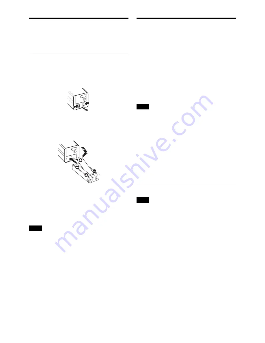
1

Squeeze the battery-holder tabs inward (in the 
direction of the arrows) and slide out the battery 
holder.

2

Insert new batteries, making sure the polarities are 
correct, and then return the battery holder to its 
original position.

Battery indication

The power status is indicated by eight level indications. 
Replace both batteries when the battery indication starts to 
flash.
Be sure to check the expiration date printed on the new 
batteries before using them.


• When BATTERY TYPE is set to TYPE1, the power 

status is indicated based on the use of new LR6 (size 
AA) Sony Alkaline batteries. An incorrect indication 
may result when a different kind of batteries, a different 
brand of batteries or old batteries are used. If you plan to 
use other kind of batteries than alkaline, set the 
BATTERY TYPE function according to the type of 
batteries to be used.

• If you plan to use the transmitter for a long period of 

time, it is recommended that you replace the batteries 
with brand new ones.

For details on BATTERY TYPE setting, see “Setting the 
battery type (BATTERY TYPE)” on page 12.

Setting the Transmission 
Channel

The transmitter provides groups of interference-free 
channels. When using multiple microphones and 
transmitters at the same time (simultaneous multi-channel 
operations) within the same area, selecting the same group 
and using a channel within that group can prevent signal 
interference.
To set the transmission channel on the transmitter, first you 
select the group and channel using the RF indicator and 
scanning functions on the receiver. Next you set the group 
and channel parameters to match the setting on the 
receiver.

• Certain transmission channels cannot be used with the 

wireless remote control function.

• “(INCOMPATIBLE WITH RF REMOTE)” will slide 

across the display during group/channel selection for 
transmission channels that cannot be used with the 
wireless remote control function.

• When a transmission channel that cannot be used with 

the wireless remote control function is selected, 
“RESTRICTED BY GP/CH SETTING” appears on the 
RF REMOTE screen and the wireless remote control 
function cannot be used. When using the wireless remote 
control function, select transmission channels for which 
“(INCOMPATIBLE WITH RF REMOTE)” does not 
appear during group/channel selection.

Selecting the group/channel


• Before doing this procedure, use the BAND function 

(see page 11)

 to set the transmitter to the bandwidth of 

the receiver you are using.

• The setting for this function cannot be changed during 

actual signal transmission. 

Set the transmitter group (GP) and channel (CH) as 
follows:

For details on groups and channels, refer to “Sony Digital 
Wireless Microphone System Frequency Lists” on the 
supplied CD-ROM.

For details on menu operation, see “Basic Menu 
Operations” on page 10.

1

Turn off the power, and then while holding down the 
SET button, turn the power on.

The signal transmission stops.

2

Press the + or – button repeatedly until the GP/CH 
indication is displayed.

Notes

Notes

Notes

Summary of Contents for DWT-P01N

Page 1: ...Digital Wireless Transmitter Operating Instructions DWT P01N 4 692 878 01 1 2016 Sony Corporation ...

Page 2: ... 12 Power save setting POWER SAVE 12 Setting the battery type BATTERY TYPE 12 Displaying the accumulated use time TIME 12 48 V power supply setting 48V 13 Setting the encrypted transmission function ENCRYPTION 13 Setting the audio codec mode CODEC MODE 13 Setting the maximum RF output power MAX RF POWER 13 Generating an internal signal INTERNAL SG 13 Locking the POWER switch POWER SW LOCK 14 Cross...

Page 3: ... receiver and the Wireless Studio control software installed on a computer connected to the receiver For example the settings of a transmitter worn under clothing can be easily changed over the wireless link Wide RF carrier frequency range The DWT P01N transmitter covers an extremely wide RF carrier frequency range Depending on the model the transmitter can cover bandwidths between 48 MHz and 72 M...

Page 4: ...shing d 48V indicator Lights up when INPUT LEVEL is set to MIC and 48 V power is being supplied to a connected microphone or other device e Display section A RF radio frequency transmission indication Indicates the current transmission status Currently transmitting Transmission stopped B RF radio frequency transmission power indication Indicates the current transmission power setting You can chang...

Page 5: ... condition For details see Battery indication on page 6 I Menu display section The status of 20 different functions are displayed here To select the function press the or button repeatedly For details see Setting Menus on page 11 f or button Selects functions or values shown on the display Holding down the button while switching on the transmitter activates the pairing operation for the wireless r...

Page 6: ...me group and using a channel within that group can prevent signal interference To set the transmission channel on the transmitter first you select the group and channel using the RF indicator and scanning functions on the receiver Next you set the group and channel parameters to match the setting on the receiver Certain transmission channels cannot be used with the wireless remote control function...

Page 7: ...tion Pairing must be done first before the wireless remote control function can be used If RESTRICTED BY GP CH SETTING appears on the RF REMOTE screen the wireless remote control function cannot be used To use the wireless remote control function select a different transmission channel For details on how to change the transmission channel see Setting the Transmission Channel on page 6 Pairing with...

Page 8: ...ireless remote control function off then on again in the RF REMOTE indication then re pairing with the transmitter change to a channel with less interference Using the Encrypted Transmission Function To prevent hacking of the signal the transmitter scrambles the signal during transmission To use this function select one of the following encrypted transmission modes Secure key mode An encryption ke...

Page 9: ... receivers are set with the same user designated password the audio signal can be decoded This mode is useful when multiple transmitters and receivers are used as a single group or when the audio signal from one transmitter is received by multiple receivers at the same time 1 Hold down the SET button until the item to be set flashes in the ENCRYPTION indication on the transmitter 2 Press the or bu...

Page 10: ...eyboards that consume more power than that cannot be used Do not leave the transmitter connected to the keyboard when not in use If you do the batteries in the transmitter will be drained more quickly Text editing should be done with the alphabet BS DEL and Enter keys Basic Menu Operations 1 Press the or button repeatedly until the function to be set appears 2 Hold down the SET button until the it...

Page 11: ...olled from the receiver and other devices For details on wireless remote control function see Using the Cross Remote on page 7 The setting for this function cannot be changed during actual signal transmission To change the setting turn off the transmitter first Then while holding down the SET button turn the power on Then change the setting after the signal transmission has stopped Be sure to sele...

Page 12: ...ing sleep the POWER indicator flashes at 2 second intervals To change back to normal operation During sleep press the SET or button You can also use the wireless remote control to change the receiver back to normal operation For details on wireless remote control function see Using the Cross Remote on page 7 If the transmitter is turned off while SLEEP is selected the setting will return to ACTIVE...

Page 13: ...expected interference resulting in more reliable transmission The audio delay durations that occur when transmitting and receiving with each mode will differ depending on the receiver s operating environment For details refer to the operating instructions supplied with the receiver The audio codec mode setting can be configured via the wireless remote control function from the receiver for example...

Page 14: ...n Channel on page 6 Setting the brightness of the display BRIGHTNESS Ten levels of brightness can be selected for the organic light emitting diode display The selectable settings are the following Dark 1 2 3 4 5 6 7 8 9 10 Bright Automatic dimming of the display DIMMER MODE The organic light emitting diode display can be set to dim or turn off after a certain amount of time AUTO OFF The display tu...

Page 15: ...15 Block Diagram Attenuator Head amp A D converter Internal SG Audio codec modulator High frequency circuit Low cut filter Digital signal processor ...

Page 16: ...transmitter set the audio input to MIC While monitoring the audio input level meter set the attenuator to an appropriate level There is distortion in the sound The attenuator is set too low for the audio input level of the transmitter While monitoring the audio input level meter set the attenuator to a level that does not produce distortion The bass is weak The frequency of the low cut filter is s...

Page 17: ...channel operation Keep the microphone at least 30 cm 11 7 8 inches away from another transmitter microphone When the distances between transmitters need to be closer than the distances above use a grouping system for multi channel systems that include both digital wireless and analog wireless devices For details refer to Sony Digital Wireless Microphone System Frequency Lists on the supplied CD RO...

Page 18: ... and DIMMER MODE set to AUTO OFF and 48V set to OFF Operating temperature 0 C to 50 C 32 F to 122 F Storage temperature 20 C to 60 C 4 F to 140 F Wireless remote control 2 4 GHz IEEE802 15 4 compliant Dimensions unit mm inches Mass Approx 245 g 8 6 oz including batteries Supplied accessories Spare battery case 1 Soft case 1 USB adapter cable 1 Before Using this Unit 3 CD ROM 1 Optional accessories...

Page 19: ...590 125 607 875 MHz TV37 Not available TV38 41 614 125 637 875 MHz U42 TV42 51 TV42 45 638 125 661 875 MHz 00 4201 638 125 MHz TV46 49 662 125 685 875 MHz TV50 51 686 125 697 875 MHz Model No Frequency band Frequency Group channel factory setting CE21 TV21 29 TV21 23 470 025 494 000 MHz 00 2101 470 125 MHz TV24 26 494 025 518 000 MHz TV27 29 518 025 542 000 MHz CE33 TV33 40 TV33 35 566 025 590 000...

Page 20: ...Sony Corporation ...

Reviews: