DSX-M50BT
6
SECTION 2
GENERAL
This section is extracted
from instruction manual.
English
Cautions
Be sure to install this unit in the dashboard of the
boat as the rear side of the unit becomes hot
during use.
ˎ
This unit is designed for negative ground (earth) 12 V
DC operation only.
ˎ
Do not get the leads under a screw, or caught in
moving parts (e.g. seat railing).
ˎ
Before making connections, turn the boat’s ignition
off to avoid short circuits.
ˎ
Connect the
yellow
and
red
power supply leads
only after all other leads have been connected.
ˎ
Run all ground (earth) leads to a common ground
(earth) point.
ˎ
Be sure to insulate any loose unconnected leads
with electrical tape for safety.
ˎ
Under the environment of potential water splash,
Sony highly recommends to protect the unit with
Waterproof Car Stereo Cover (not supplied).
While an iPod or USB device is connected, the
Waterproof Car Stereo Cover cannot be fully closed.
Avoid splashing water on the unit.
Notes on the power supply lead (yellow)
ˎ
When connecting this unit in combination with other
stereo components, the connected boat circuit’s
rating must be higher than the sum of each
component’s fuse.
ˎ
When no boat circuits are rated high enough,
connect the unit directly to the battery.
A
*
B
C
Equipment used in illustrations (not supplied)
Appareils utilisés dans les illustrations (non fournis)
Equipo utilizado en las ilustraciones (no suministrado)
*
4
Front speaker
Haut-parleur avant
Altavoz frontal
*
4
Power amplifier
Amplificateur de puissance
Amplificador de potencia
*
4
Rear speaker
Haut-parleur arrière
Altavoz posterior
*
1
RCA pin cord (not supplied).
*
2
Separate adaptor may be required.
*
3
Supplied with the marine remote commander.
*
4
not waterproof
*
1
Cordon à broche RCA (non fourni).
*
2
L’utilisation d’un adaptateur pourrait être nécessaire.
*
3
Fourni avec la télécommande marine.
*
4
non étanche
*
1
Cable con terminales RCA (no suministrado).
*
2
Puede requerirse un adaptador independiente.
*
3
Suministrado con el mando a distancia subacuático.
*
4
no es resistente al agua
REM OUT
Max. supply current 0.4 A
Courant max. fourni 0,4 A
Corriente máx. de alimentación de 0,4 A
Fuse (10 A)
Fusible (10 A)
Fusible (10 A)
Blue/white striped
Rayé bleu/blanc
Con rayas azules y blancas
ACC
BATTERY
ʔ
Red
Rouge
Rojo
Yellow
Jaune
Amarillo
White
Blanc
Blanco
Green
Vert
Verde
Purple
Violet
Morado
White/black striped
Rayé blanc/noir
Con rayas blancas y negras
Gray/black striped
Rayé gris/noir
Con rayas grises y negras
Green/black striped
Rayé vert/noir
Con rayas verdes y negras
Gray
Gris
Gris
Left
Gauche
Izquierdo
Right
Droit
Derecho
Left
Gauche
Izquierdo
Right
Droit
Derecho
Purple/black striped
Rayé violet/noir
Con rayas moradas y negras
from boat antenna (aerial)
à partir de l’antenne
du bateau
desde la antena del barco
Black
Noir
Negro
*
1
*
3
RM-X11M
Marine remote commander
Télécommande marine
Mando a distancia subacuático
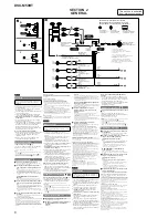
Connection diagram (
)
ɞ
To battery or distribution block ground
First connect the black ground (earth) lead, then connect the
yellow and red power supply leads.
ɟ
To the power antenna (aerial) control lead or
power supply lead of antenna (aerial) booster
Notes
ˎ
It is not necessary to connect this lead if there is no power
antenna (aerial) or antenna (aerial) booster, or with a
manually-operated telescopic antenna (aerial).
ˎ
When your boat has a built-in FM/AM antenna (aerial) in the
rear/side glass, see “Notes on the control and power supply
leads.”
To AMP REMOTE IN of an optional power
amplifier
This connection is only for amplifiers and a power antenna
(aerial). Connecting any other system may damage the unit.
ɠ
To the +12 V power terminal which is energized
in the accessory position of the ignition switch
Notes
ˎ
If there is no accessory position, connect to the +12 V power
(battery) terminal which is energized at all times.
Be sure to connect the black ground (earth) lead to the battery
or distribution block ground first.
ˎ
When your boat has a built-in FM/AM antenna (aerial) in the
rear/side glass, see “Notes on the control and power supply
leads.”
ɡ
To the +12 V power terminal which is energized
at all times
Be sure to connect the black ground (earth) lead to the battery
or distribution block ground first.
Notes on the control and power supply leads
ˎ
REM OUT lead (blue/white striped) su12 V DC when you turn
on the unit.
ˎ
When your boat has built-in FM/AM antenna (aerial) in the rear/
side glass, connect REM OUT lead (blue/white striped) or the
accessory power supply lead (red) to the power terminal of the
existing antenna (aerial) booster. For details, consult your dealer.
ˎ
A power antenna (aerial) without a relay box cannot be used with
this unit.
Connection example (
)
Subwoofer Easy Connection (
ǵ
-C)
You can use a subwoofer without a power amplifier
when it is connected to a rear speaker cord.
* Do not connect a speaker in this connection.
Notes
ˎ
Be sure to connect the ground (earth) lead before connecting the
amplifier (
ǵ
-A).
ˎ
The alarm will only sound if the built-in amplifier is used (
ǵ
-A).
ˎ
Be sure to connect a 4 - 8 ohm subwoofer. Do not connect a
speaker to the other rear speaker cord (
ǵ
-C).
Memory hold connection
When the yellow power supply lead is connected, power will always
be supplied to the memory circuit even when the ignition switch is
turned off.
Notes on speaker connection
ˎ
Before connecting the speakers, turn the unit off.
ˎ
Use speakers with an impedance of 4 to 8 ohms, and with
adequate power handling capacities to avoid its damage.
ˎ
Do not connect the speaker terminals to the boat chassis, or
connect the terminals of the right speakers with those of the left
speaker.
ˎ
Do not connect the ground (earth) lead of this unit to the negative
(–) terminal of the speaker.
ˎ
Do not attempt to connect the speakers in parallel.
ˎ
Connect only passive speakers. Connecting active speakers (with
built-in amplifiers) to the speaker terminals may damage the unit.
ˎ
To avoid a malfunction, do not use the built-in speaker leads
installed in your boat if the unit shares a common negative (–) lead
for the right and left speakers.
ˎ
Do not connect the unit’s speaker leads to each other.
Note on connection
If speaker and amplifier are not connected correctly, “ERROR” appears
in the display. In this case, make sure the speaker and amplifier are
connected correctly.
Diagrama de conexión (
)
ɞ
A la conexión a masa de la batería o del bloque
de distribución
Conecte primero el cable de conexión a masa negro, y después
los cables amarillo y rojo de fuente de alimentación.
ɟ
Al cable de control de la antena motorizada o al
cable de fuente de alimentación del
amplificador de señal de la antena
Notas
ˎ
Si no se dispone de antena motorizada ni de amplificador de
señal de la antena, o se utiliza una antena telescópica
accionada manualmente, no será necesario conectar este
cable.
ˎ
Si el barco tiene una antena de FM/AM incorporada en el
cristal trasero o lateral, consulte “Notas sobre los cables de
control y de fuente de alimentación”.
A
AMP REMOTE IN de un amplificador de
potencia opcional
Esta conexión es sólo para amplificadores y una antena
motorizada. La conexión de cualquier otro sistema puede dañar
la unidad.
ɠ
Al terminal de alimentación de +12 V que recibe
energía en la posición de accesorio del
interruptor de encendido
Notas
ˎ
Si no hay posición de accesorio, conéctelo al terminal de
alimentación (batería) de +12 V que recibe energía sin
interrupción.
Asegúrese de conectar primero el cable de conexión a masa
negro a la batería o a la toma a masa del bloque de
distribución.
ˎ
Si el barco tiene una antena de FM/AM incorporada en el
cristal trasero o lateral, consulte “Notas sobre los cables de
control y de fuente de alimentación”.
ɡ
Al terminal de alimentación de +12 V que recibe
energía sin interrupción
Asegúrese de conectar primero el cable de conexión a masa
negro a la batería o a la toma a masa del bloque de distribución.
Notas sobre los cables de control y de fuente de alimentación
ˎ
El cable REM OUT (rayado azul y blanco) suministra cc de +12 V al
encender la unidad.
ˎ
Si el barco tiene una antena FM/AM integrada en el cristal posterior
o lateral, conecte el cable REM OUT (rayado azul y blanco) o el cable
de fuente de alimentación auxiliar (rojo) al terminal de alimentación
del amplificador de señal de la antena existente. Para obtener más
detalles, consulte a su distribuidor.
ˎ
Con esta unidad no es posible utilizar una antena motorizada sin
caja de relé.
Conexión para protección de la memoria
Si conecta el cable de fuente de alimentación amarillo, el circuito de
la memoria recibirá siempre alimentación, aunque apague el
interruptor de encendido.
Notas sobre la conexión de los altavoces
ˎ
Antes de conectar los altavoces, desconecte la alimentación de la
unidad.
ˎ
Utilice altavoces con una impedancia de 4 a 8 Ω, con la capacidad
de potencia adecuada para evitar que se dañen.
ˎ
No conecte los terminales de altavoz al chasis del barco, ni conecte
los terminales del altavoz derecho con los del izquierdo.
ˎ
No conecte el cable de conexión a masa de esta unidad al terminal
negativo (–) del altavoz.
ˎ
No intente conectar los altavoces en paralelo.
ˎ
Conecte solamente altavoces pasivos. Si conecta altavoces activos
(con amplificadores incorporados) a los terminales de altavoz,
puede dañar la unidad.
ˎ
Para evitar fallas de funcionamiento, no utilice los cables de altavoz
incorporados instalados en el barco si la unidad comparte un cable
negativo común (–) para los altavoces derecho e izquierdo.
ˎ
No conecte los cables de altavoz de la unidad entre sí.
Nota sobre la conexión
Si el altavoz y el amplificador no están conectados correctamente,
aparecerá “ERROR” en la pantalla. Si es así, compruebe la conexión
de ambos dispositivos.
Français
Mises en garde
Installez cet appareil sur le tableau de bord du
bateau, car l’arrière de l’appareil chauffe en cours
d’utilisation.
ˎ
Cet appareil est exclusivement conçu pour
fonctionner sur une tension de 12 V CC avec masse
négative.
ˎ
Évitez de fixer des vis sur les câbles ou de coincer
ceux-ci dans des pièces mobiles (par exemple,
armature de siège).
ˎ
Avant d’effectuer les raccordements, coupez le
contact du bateau pour éviter les courts-circuits.
ˎ
Raccordez les câbles d’alimentation
jaune
et
rouge
seulement après avoir terminé tous les autres
raccordements.
ˎ
Rassemblez tous les câbles de mise à la masse en
un point de masse commun.
ˎ
Pour des raisons de sécurité, veillez à isoler avec du
ruban isolant tout câble libre non raccordé.
ˎ
Si l’appareil risque d’être exposé à des
éclaboussures d’eau, Sony recommande fortement
de le protéger avec une housse imperméable pour
chaîne stéréo de voiture (non fournie).
Lorsqu’un iPod ou un périphérique USB est raccordé,
la housse imperméable pour chaîne stéréo de
voiture ne peut pas se fermer complètement. Évitez
d’exposer l’appareil à des éclaboussures d’eau.
Remarques sur le câble d’alimentation (jaune)
ˎ
Lorsque cet appareil est raccordé à d’autres
éléments stéréo, la valeur nominale du circuit du
bateau raccordé doit être supérieure à la somme des
fusibles de chaque élément.
ˎ
Si aucun circuit du bateau n’est assez puissant,
raccordez directement l’appareil à la batterie.
Exemple de raccordement (
)
Raccordement facile d’un caisson de graves (
ǵ
-C)
Vous pouvez utiliser un caisson de graves sans
amplificateur de puissance lorsque vous effectuez le
raccordement à un cordon de haut-parleur arrière.
* Ne raccordez pas un haut-parleur avec cette connexion.
Remarques
ˎ
Raccordez d’abord le câble de mise à la masse avant de raccorder
l’amplificateur (
ǵ
-A).
ˎ
L’alarme est émise uniquement lorsque l’amplificateur intégré est
utilisé (
ǵ
-A).
ˎ
Assurez-vous de raccorder un caisson de graves de 4 - 8 ohms. Ne
raccordez pas de haut-parleur à l’autre cordon de haut-parleur
arrière (
ǵ
-C).
Remarques
ˎ
Il n’est pas nécessaire de raccorder ce câble s’il n’y a pas
d’antenne électrique ni d’amplificateur d’antenne, ou avec une
antenne télescopique manuelle.
ˎ
Si votre bateau est équipé d’une antenne FM/AM intégrée
dans la vitre arrière/latérale, voir « Remarques sur les câbles de
commande et d’alimentation ».
Au niveau de AMP REMOTE IN de l’amplificateur
de puissance en option
Ce raccordement s’applique uniquement aux amplificateurs et à
une antenne électrique. Le branchement de tout autre système
risque d’endommager l’appareil.
ɠ
À la borne d’alimen12 V qui est
alimentée quand la clé de contact est sur la
position accessoires
Remarques
ˎ
S’il n’y a pas de position accessoires, raccordez la borne
d’alimentation (batterie) +12 V qui est alimentée en
permanence.
Commencez par raccorder le câble de mise à la masse noir à la
batterie ou au répartiteur de terre.
ˎ
Si votre bateau est équipé d’une antenne FM/AM intégrée
dans la vitre arrière/latérale, voir « Remarques sur les câbles de
commande et d’alimentation ».
ɡ
À la borne d’alimen12 V qui est
alimentée en permanence
Commencez par raccorder le câble de mise à la masse noir à la
batterie ou au répartiteur de terre.
Remarques sur les câbles de commande et d’alimentation
ˎ
Le câble REM OUT (rayé bleu/blanc) fournit une alimentation de
+12 V CC lorsque vous mettez l’appareil en marche.
ˎ
Lorsque votre bateau est équipé d’une antenne FM/AM intégrée
dans la vitre arrière/latérale, raccordez le câble REM OUT (rayé
bleu/blanc) ou le câble d’alimentation des accessoires (rouge) à la
borne d’alimentation de l’amplificateur d’antenne existant. Pour
plus de détails, consultez votre détaillant.
ˎ
Une antenne électrique sans boîtier de relais ne peut pas être
utilisée avec cet appareil.
Raccordement pour la conservation de la mémoire
Lorsque le câble d’alimentation jaune est raccordé, le circuit de la
mémoire est alimenté en permanence même si la clé de contact est
sur la position d’arrêt.
Remarques sur le raccordement des haut-parleurs
ˎ
Avant de raccorder les haut-parleurs, éteignez l'appareil.
ˎ
Utilisez des haut-parleurs ayant une impédance de 4 à 8 ohms avec
une capacité électrique adéquate pour éviter de les endommager.
ˎ
Ne raccordez pas les bornes du système de haut-parleurs au
châssis du bateau et ne raccordez pas les bornes du haut-parleur
droit à celles du haut-parleur gauche.
ˎ
Ne raccordez pas le câble de mise à la masse de cet appareil à la
borne négative (–) du haut-parleur.
ˎ
N’essayez pas de raccorder les haut-parleurs en parallèle.
ˎ
Raccordez uniquement des haut-parleurs passifs. Le raccordement
de haut-parleurs actifs (avec amplificateurs intégrés) aux bornes
des haut-parleurs peut endommager l’appareil.
ˎ
Pour éviter tout problème de fonctionnement, n’utilisez pas les
câbles des haut-parleurs intégrés installés dans votre bateau si
l’appareil possède un câble négatif commun (–) pour les
haut-parleurs droit et gauche.
ˎ
Ne raccordez pas entre eux les câbles des haut-parleurs de
l’appareil.
Remarque sur le raccordement
Si le haut-parleur et l’amplificateur ne sont pas raccordés
correctement, le message « ERROR » s’affiche. Dans ce cas,
assurez-vous que les haut-parleurs et l’amplificateur sont bien
raccordés.
Español
Precauciones
Asegúrese de instalar la unidad en el tablero del
barco, ya que la parte posterior de la unidad se
calienta durante el uso.
ˎ
Esta unidad ha sido diseñada para alimentarse sólo
con cc de 12 V de masa negativa.
ˎ
No coloque los cables debajo de ningún tornillo, ni
los aprisione con partes móviles (p. ej. los rieles del
asiento).
ˎ
Antes de realizar las conexiones, desactive el
encendido del barco para evitar cortocircuitos.
ˎ
Conecte los cables de fuente de alimentación
amarillo
y
rojo
solamente después de haber
conectado los demás.
ˎ
Conecte todos los cables de conexión a masa a un
punto común.
ˎ
Por razones de seguridad, asegúrese de aislar con
cinta aislante los cables sueltos que no estén
conectados.
ˎ
En caso de riesgo accidental de salpicaduras de
agua, Sony recomienda encarecidamente proteger
la unidad con una Cubierta resistente al agua para el
reproductor estéreo (no suministrado).
Mientras el iPod o el dispositivo USB está conectado,
la Cubierta resistente al agua para el reproductor
estéreo no puede cerrarse por completo. Evite tirar
agua sobre la unidad.
Ejemplo de conexiones (
)
Conexión sencilla del altavoz potenciador de graves
(
ǵ
-C)
Cuando el altavoz potenciador de graves está
conectado al cable de altavoz posterior, puede usarlo
sin un amplificador de potencia.
* No conecte un altavoz a esta conexión.
Notas
ˎ
Asegúrese de conectar primero el cable de conexión a masa antes
de realizar la conexión del amplificador (
ǵ
-A).
ˎ
La alarma sonará únicamente si se utiliza el amplificador
incorporado (
ǵ
-A).
ˎ
Asegúrese de conectar un altavoz potenciador de graves de 4 a
8 Ω. No conecte un altavoz al otro cable de altavoz posterior (
ǵ
-C).
Notas sobre el cable de fuente de alimentación
(amarillo)
ˎ
Cuando conecte esta unidad en combinación con
otros componentes estéreo, la capacidad nominal
del circuito conectado del barco debe ser superior a
la suma del fusible de cada componente.
ˎ
Si no hay circuitos del barco con capacidad nominal
suficientemente alta, conecte la unidad
directamente a la batería.
Schéma de raccordement (
)
ɞ
Vers la batterie ou le répartiteur de terre
Branchez d’abord le câble de mise à la masse noir et, ensuite, les
câbles d’alimentation jaune et rouge.
ɟ
Au câble de commande d’antenne électrique ou
au câble d’alimentation de l’amplificateur
d’antenne
Remarques
é
â
Summary of Contents for DSX-M50BT
Page 12: ...DSX M50BT 12 MEMO ...
Page 33: ...MEMO DSX M50BT 33 ...


