DSX-M50BT
DSX-M50BT
15
15
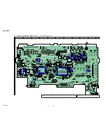
THIS NOTE IS COMMON FOR PRINTED WIRING BOARDS AND SCHEMATIC DIAGRAMS.
(In addition to this, the necessary note is printed in each block.)
For Printed Wiring Boards.
Note:
•
X
: Parts extracted from the component side.
•
Y
: Parts extracted from the conductor side.
•
f
: Internal component.
•
: Pattern from the side which enables seeing.
(The other layers’ patterns are not indicated.)
• Waveforms
– MAIN Board –
For Schematic Diagrams.
Note:
• All capacitors are in
μ
F unless otherwise noted. (p: pF)
50 WV or less are not indicated except for electrolytics
and tantalums.
• All resistors are in
and
1
/
4
W or less unless otherwise
speci
fi
ed.
•
f
: internal component.
•
C
: panel designation.
•
A
: B+ Line.
• Power voltages is dc 14.4V and fed with regulated dc
power supply from ACC and BATT cords.
• Voltages and waveforms are dc with respect to ground
under no-signal (detuned) conditions.
no mark
: TUNER (FM)
( ) : BT AUDIO
[ ] : BT PHONE
• Voltages are taken with a VOM (Input impedance 10 M
).
Voltage variations may be noted due to normal production
tolerances.
• Waveforms are taken with a oscilloscope.
Voltage variations may be noted due to normal production
tolerances.
• Circled numbers refer to waveforms.
• Signal path.
F
:
AUDIO
f
:
TUNER
d
:
USB
E
:
AUX
a
:
Bluetooth
N
:
MIC
Caution:
Pattern face side:
(Conductor Side)
Parts face side:
(Component Side)
Parts on the pattern face side seen
from the pattern face are indicated.
Parts on the parts face side seen from
the parts face are indicated.
• Indication of transistor.
C
B
These are omitted.
E
Q
Note 2:
When the complete MAIN board is replaced, it is
necessary to con
fi
rm operation. Refer to “BLUE-
TOOTH FUNCTION CHECKING METHOD US-
ING A CELLULAR PHONE” on page 5.
Note 1:
When the complete MAIN board is replaced, the
destination setting is necessary. Refer to “NOTE OF
REPLACING THE COMPLETE MAIN BOARD
OR SYSTEM CONTROLLER (IC101)” on page 4.
1
IC201
ug
(X12OUT)
2 V/DIV, 50 ns/DIV
83 ns
2.7 Vp-p
2
IC101
9
(XOUT)
2 V/DIV, 20
P
s/DIV
30.4
P
s
2.7 Vp-p
3
IC101
qa
(OSCOUT)
2 V/DIV, 50 ns/DIV
126 ns
3.5 Vp-p
4
IC501
1
(BST)
10 V/DIV, 2
P
s/DIV
2.4
P
s
16.4 Vp-p
Note 2:
When the complete MAIN board is replaced, it is
necessary to con
fi
rm operation. Refer to “BLUE-
TOOTH FUNCTION CHECKING METHOD US-
ING A CELLULAR PHONE” on page 5.
Note 1:
When the complete MAIN board is replaced, the
destination setting is necessary. Refer to “NOTE OF
REPLACING THE COMPLETE MAIN BOARD
OR SYSTEM CONTROLLER (IC101)” on page 4.
Summary of Contents for DSX-M50BT
Page 12: ...DSX M50BT 12 MEMO ...
Page 33: ...MEMO DSX M50BT 33 ...


