background image

2-1 Control Panels

Chapter 2

Location and Function of Parts

2-2

Chapter 2

Location and Function of Parts

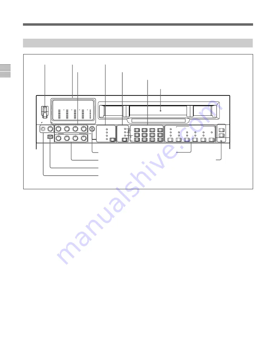
2-1-1 Upper Control Panel

-20

PHONES

DISPLAY

FULL/FINE

CH-1

CH-2

CH-3

CH-4

VIDEO

POWER

REC

PULL FOR VARIABLE

PB

ON

OFF

-80

-20

-30
-40

-10

0

dB

-80

-20

-30
-40

-10

0

dB

-80

-30
-40

-10

0

dB

-80

-20

-30
-40

-10

0

dB

0

-2

2

-4

COMPOSITE

COMPONENT

(Y-R,B)

SDI

VIDEO INPUT SELECT

AUDIO SELECT

INPUT

EXT

MIXING

L

R

CH-1

CH-2

CH-3

CH-4

LTC

TC

AUTO

VITC

INT

EXT

PRESET

REGEN

FREE

RUN
REC
RUN

DF

NDF

ON

1(9P)

TC GENERATOR

VITC

DIGITAL

REMOTE

SDT I

(VIDEO&AUDIO)

MONITOR

SDI

AES/EBU

REC CH

ANALOG

2(50P)

RS232C

1

 POWER switch

This powers the unit on and off. When the unit is
powered on, the level meters 

2

 and the fluorescent

display in the lower control panel light.
To power the unit off, press the side of the POWER
switch marked “OFF”.

2

 Level meters

These show the audio levels of channels 1 to 4
(recording levels in recording mode or E-E mode

 1)

 and

playback level in playback mode) and the video levels
of input composite video signals.
There are two modes for audio level indications:
FULL and FINE, selected by the DISPLAY FULL/
FINE switch 

9

.

1) E-E mode: Abbreviation of “Electric-to-Electric mode”.

In this mode, video and audio signals input to the VTR
are output after passing through internal electric circuits,
but not through magnetic conversion circuits such as
heads and tapes. This can be used to check input signals
and for adjusting input signal levels.

..........................................................................................................................................................................................................

3

 REC (recording) controls

These individually adjust the recording levels on
channels 1 to 4.
To set the recording level, put the unit in E-E mode,
pull out the control knobs and adjust the level while
watching the level meters 

2

.

When the control knobs are pushed in, the recording
levels return to the preset levels (0 dBm reference level
for an input of +4 dBm), and cannot be adjusted.
These controls do not function when SDTI video input
is selected.

For details of selecting the E-E mode, see the description of
the REC button in the tape transport control section (see
page 2-14) and the PB.EE button in the monitor/menu/
display setting section (see page 2-8).

1

POWER
switch

2

Level meters

3

REC controls

4

VIDEO INPUT SELECT switch and indicators

5

Audio selection function selector switch and indicators

7

VIDEO control

8

PB controls

9

DISPLAY FULL/FINE switch

0

PHONES jack and control

Time code setting
section

!™

REMOTE buttons and RS-232C indicator

6

Audio signal selection buttons

Cassette compartment

Summary of Contents for DNW-75

Page 1: ...DIGITAL VIDEOCASSETTE RECORDER DNW 75 75P OPERATION MANUAL English 1st Edition Revised 4 ...

Page 2: ...the limits for a digital device pursuant to Subpart B of Part 15 of FCC Rules For the customers in Europe This product with the CE marking complies with both the EMC Directive 89 336 EEC and the Low Voltage Directive 73 23 EEC issued by the Commission of the European Community Compliance with these directives implies conformity to the following European standards EN60065 Product Safety EN55103 1 E...

Page 3: ...3 5 2 Inserting and Ejecting Cassettes 3 10 3 5 3 Preventing Accidental Erasure of Recordings 3 11 Chapter 4 Recording and Playback 4 1 Recording 4 1 4 1 1 Preparations for Recording 4 1 4 1 2 Recording Time Code and User Bit Values 4 2 4 1 3 Recording Procedure 4 5 4 2 Playback 4 6 4 2 1 Preparations for Playback 4 6 4 2 2 Playback Feed Play Procedures 4 7 4 2 3 Dynamic Motion Control DMC Playbac...

Page 4: ...rks 6 8 Chapter 7 Menu System 7 1 Menu System Configuration 7 1 7 2 Basic Menu 7 1 7 2 1 Items in the Basic Menu 7 1 7 2 2 Basic Menu Operations 7 4 7 3 Extended Menu 7 9 7 3 1 Items in the Extended Menu 7 9 7 3 2 Extended Menu Operations 7 25 Chapter 8 Maintenance and Inspection 8 1 Removing a Cassette When Tape Slack Occurs 8 1 8 2 Head Cleaning 8 1 8 3 Error Messages 8 2 8 4 Moisture Condensati...

Page 5: ...rting nonlinear editing systems and server systems Compared with analog Betacam the Betacam SX format reduces the tape speed to approximately one half The drum rotates at 75 revolutions per second recording two frames of video data and four channels of digital audio in ten diagonal tracks The longitudinal control and time code tracks are the same as in the analog Betacam format Head configuration ...

Page 6: ...range of indications In addition to the LED display which shows the operating status and current settings of this unit and connected equipment a fluorescent display displays numerical values including time code user bits editing IN and OUT points editing durations error messages and setup menu information Selection of external internal time code You can record using either an external time code or...

Page 7: ...oadcasting station Betacam SX camcorder Digital cassette Microphone Digital SDTI SDI Analog composite Analog audio Video monitor Audio monitor SNG a system Digital modulator Digital demodulator a SNG Satellite News Gathering Analog composite DNW 75 75P Digital cassette BVE series editor Tape control Analog composite Audio monitor Microphone Analog composite component DNW 75 75P Video monitor VTR w...

Page 8: ......

Page 9: ...panel Lower control panel Subsidiary control panel Chapter 2 Location and Function of Parts VI TC UB INTRP A IN DF LTC VITC 8F 4F 2F CONFI ON TCG TOTAL REMAIN 525 625 EVENT A OUT Upper control panel See page 2 2 Subsidiary control panela See page 2 16 Lower control panel See page 2 7 a To reveal the subsidiary control panel pull the lower control panel forward ...

Page 10: ...1 E E mode Abbreviation of Electric to Electric mode In this mode video and audio signals input to the VTR are output after passing through internal electric circuits but not through magnetic conversion circuits such as heads and tapes This can be used to check input signals and for adjusting input signal levels 3 REC recording controls These individually adjust the recording levels on channels 1 ...

Page 11: ... INPUT indicator and MONITOR indicator cyclically and selects the function of the audio signal selection buttons When the MIXING indicator is lit You can use the EXT and REC CH rows of the audio signal selection buttons to switch the audio signals to be recorded or carry out mixing When the INPUT indicator is lit You can use the SDI AES EBU and ANALOG L R rows of the audio signal selection buttons...

Page 12: ...layer channel 1 signals on recorder channel 2 rotate the CH 1 REC knob while viewing the level meter for CH 2 When the INPUT indicator is lit For each channel press the button in the SDI row the AES EBU row or the ANALOG row The pressed button lights and the corresponding audio input signal is selected However when the video input signals selected with the VIDEO INPUT SELECT switch are SDTI the au...

Page 13: ... The VITC time code included in the input video signal PRESET REGEN preset regenerated switch and indicators This switch makes the following selection for the internal time code generator PRESET The initial value of the time code produced by the internal time code generator can be preset by a control panel operation or by remote control from a device connected to the REMOTE1 IN 9P connector REGEN ...

Page 14: ...MOTE buttons and RS 232C indicator Press one of these buttons to select the device controlling this unit 1 9P This unit is controlled by the device connected to the REMOTE1 IN 9P or REMOTE1 OUT 9P connector The button lights 2 50P This unit is controlled by the device connected to the REMOTE PARALLEL I O 50P connector The button lights RS 232C indicator This indicator lights when this unit is cont...

Page 15: ...gnals time code signals and so forth are recorded together ASSEMBLE CH 1 VIDEO TIME CODE INSERT CH 2 CH 3 CH 4 2 VIDEO button To select the video signal for insert editing2 press this button turning it on 3 TIME CODE button To select time code for insert editing press this button turning it on 4 CH 1 to CH 4 channel 1 to channel 4 buttons For insert editing to select audio channels 1 to 4 press th...

Page 16: ...enu operations see Chapter 7 Menu System and for details of setting time code and user bit values see Section 4 1 2 Recording Time Code and User Bit Values page 4 2 7 HOLD button To stop updating of the time code or user bit value in the fluorescent display that is to hold the display press this button turning it on To set a time code or user bit value first press this button to hold the value 8 C...

Page 17: ...ording to the setting of the CTL TC UB button in the monitor menu display setting section 2 and the setting of the TC switch in the upper control panel It is also used to display an IN point or audio IN point a duration error messages setup menus and so forth For details of the selection of CTL count time code value or user bit value see the description of the CTL TC UB button on the previous page...

Page 18: ...N indicator DF drop frame indicator This lights when a displayed time code value is in drop frame mode LTC VITC indicators Regardless of the display in the time data display area 1 these indicators light when the corresponding time code values are being read or recorded during recording CAPSTAN LOCK 8F 4F 2F 8 fields 4 fields 2 fields indicators The indicator lights corresponding to the mode selec...

Page 19: ...cord inhibit plug on the cassette as shown in the following table When this indicator is on recording on tape is prohibited REC INHIBIT indicator indications a It is possible to make a setting extended menu item 107 so that in this case the indicator flashes 3 PLAYER button and RECORDER button When you carry out editing using a VTR connected to the REMOTE 1 IN 9P or REMOTE 1 OUT 9P connector as th...

Page 20: ...correspondingly Capstan override function 5 PREVIEW button After edit point setting to preview the editing results on the monitor before recording press this button turning it on If the IN point is not set the preview is carried out with the point where you pressed this button as the IN point During the preview it is lit and when the preview ends it flashes 6 AUTO automatic EDIT button After edit ...

Page 21: ...g it on In standby mode the drum is rotating and the tape is in contact with the drum As a result recording or playback can start immediately To end standby mode press the STANDBY button turning it off If 8 minutes value can be varied using extended menu item 501 elapse in standby mode the unit automatically switches out of standby mode to protect the tape Fault display function When an analog rec...

Page 22: ...rning it on When you stop playback the unit switches either to still playback or to E E mode according to setup menu settings and the settings of the PB EE button and PB button Fault display function This flashes in the following cases related to reference signals When the OUT REF switch on the subsidiary control panel is set to INPUT VIDEO and there is no input video signal When the OUT REF switc...

Page 23: ...buttons 5 SHUTTLE VAR and JOG indicators When searching in shuttle mode the SHUTTLE VAR indicator lights and when searching in jog mode the JOG indicator lights Shuttle Press the SHUTTLE button or the search dial so that the SHUTTLE button lights then turn the search dial Playback is carried out at a speed determined by the position of the search dial The playback speed range is 78 to 78 times nor...

Page 24: ...ing on the combination of the setting of extended menu item 309 and the operating state of the unit REF Use the signal input to the REF VIDEO INPUT connector as the reference signal During recording input digital audio and video signals must be synchronized with this signal INPUT VIDEO Use the input video signal selected by the VIDEO INPUT SELECT switch as the reference signal Note Operating this ...

Page 25: ...ately below When it is set to MANUAL you can use the knob to adjust the setup level 525 60 system or black level 625 50 system PRESET Regardless of the position of the knob the setup level 525 60 system or black level 625 50 system is set to the reference value MANUAL You can adjust the setup level 525 60 system in the range 30 IRE1 or the black level 625 50 system in the range 210 mV 8 CHROMA chr...

Page 26: ...recorded with a composite signal as source no horizontal shift H shift of the image occurs Select this position for editing and playback of composite signals when video phase continuity at edit points is required or for A B roll editing 8FD 625 50 This position is not normally used in a 525 60 system If you select this position in a 625 50 system the tape playback output is subject to virtual colo...

Page 27: ... LEVEL 600Ω LOW HIGH OFF ON CH4 LEVEL 600Ω LOW HIGH OFF ON CH3 LEVEL 600Ω LOW HIGH OFF ON CH2 LEVEL IN OUT CH1 2 CH3 4 AUDIO OUTPUT AES EBU PARALLEL I O 50P REMOTE 2 CH1 2 CH3 4 CH1 CH2 CH3 CH4 R L SDTI OUTPUT 1 2 2 2 Connector Panel Cooling fan 2 Analog video input output section See page 2 20 1 Analog audio input output section See page 2 20 3 Digital input output section See page 2 21 4 Time co...

Page 28: ...F position and otherwise to the ON position 3 COMPONENT VIDEO INPUT connectors BNC type Input analog component video signals Y R Y B Y 4 COMPOSITE VIDEO OUTPUT connectors BNC type These output analog composite video signals When the CHARACTER switch on the subsidiary control panel is set to ON connector 3 SUPER outputs a signal with superimposed time code menu settings alarm messages and other tex...

Page 29: ... signals are output 5 COMPONENT VIDEO OUTPUT connectors BNC type These output analog component video signals Y R Y B Y 3 Digital input output section 1 SDI Serial Digital Interface INPUT connectors BNC type Input D1 format digital video audio signals Of the two connectors the upper one is for input and the lower one is for a active through connection 2 SDI Serial Digital Interface OUTPUT connector...

Page 30: ...ype Input up to two sets 4 channels channels 1 2 and 3 4 of AES EBU format digital audio signals 2 AUDIO OUTPUT AES EBU connectors BNC type Output up to two sets 4 channels channels 1 2 and 3 4 of AES EBU format digital audio signals 3 REMOTE1 OUT 9P connector D sub 9 pin This provides the loop through output for remote control signals from the REMOTE1 IN 9P connector 2 4 RS 232C connector D sub 9...

Page 31: ...an external device For details refer to the Installation Manual 7 Power supply section 1 AC IN connector 2 BREAKER button AC IN BREAKER 3 Ground terminal 1 AC IN connector Use the optional power cord to connect this to an AC outlet 2 BREAKER button This jumps out if an excess current flows on the primary side of the AC power circuit 3 Ground terminal Connect this to ground ...

Page 32: ......

Page 33: ...VR 2100 D1 component digital VTR as recorder REMOTE IN 9P REMOTE IN 9P REMOTE 1 SERIAL V A IN REMOTE OUT 9P SDI OUTPUT SDI OUTPUT 2 SDI OUTPUT 3 SDI INPUT 3 1 Connections to External Devices Chapter 3 Preparations 3 1 1 Connections to Digital Devices DNW 75 75P Player DNW 75 75P BVM 1454 Series Video Monitor DVR 2100 Digital VTR Recorder ...

Page 34: ...EO INPUT COMPONENT VIDEO INPUT COMPONENT COMPOSITE VIDEO OUTPUT REMOTE 9P AUDIO INPUT CH1 CH4 REMOTE1 IN 9P 3 1 2 Connections to Analog Devices Video monitor AUDIO INPUT CH1 to CH4 LEVEL switches set according to the analog input level and the impedance See page 2 20 75 Ω termination switch set to OFF when using an analog composite video signal bridge connection and otherwise to ON DNW A100 A100P ...

Page 35: ...pending on the settings of the OUT REF switch on the subsidiary control panel and extended menu item 309 and the input signal selection the external synchronization status is as shown in the following flowchart Start EXT AUTO1 Setting of extended menu item 309 INPUT VIDEO REF Yes No Is a signal input to the REF VIDEO INPUT connector Yes No Synchronize to the input video signal selected with the VI...

Page 36: ...depends on the operational status of the VTR as shown in the following flowchart Start EXT Setting of extended menu item 309 Setting of the OUT REF switch INPUT VIDEO REF Yes No Yes No Is a signal input to the REF VIDEO INPUT connector Yes No Lock the servo to the input video signal selected with the VIDEO INPUT SELECT switch No external synchronization AUTO1 AUTO2 Currently recording or editing S...

Page 37: ...g from an external VTR player 3 2 3 Connecting Reference Signals Connect reference signals as shown below according to the way in which the unit is to be used Reference signal DNW 75 75P recorder 75 Ω termination switch OFF 75 Ω termination switch ON SDI INPUT REF VIDEO INPUT Reference signal Switcher or signal generator DNW 75 75P 75 Ω termination switch ON DVW A510 A510P 510 510P series player ...

Page 38: ...parations 3 6 Chapter 3 Preparations 3 2 Reference Signals for Video Output and Servo System Connections for playback SDI OUTPUT REF VIDEO INPUT Reference signal Serial monitor DNW 75 75P 75 Ω termination switch ON ...

Page 39: ...Items relating to tape protection Items relating to the time code generator Items relating to video control Items relating to audio control Items relating to digital processing For detailed information about the items except for the basic menu items relating to the hours meter of these menus and how to use them see Chapter 7 Menu System For details of the basic menu items relating to the hours met...

Page 40: ... of basic menu item 005 allows different time data to be displayed in the bottom line of the display For details of the basic menu see Section 7 2 1 Items in the Basic Menu page 7 1 1 Types of time data Note If the time data or user s bits cannot be read correctly they will be displayed with an asterisk For example T R U R T R or U R Display Meaning CTL CTL counter data TCR LTC reader time code UB...

Page 41: ...g automatic editing Display Block A Block B Operation mode UNTHREAD Cassette is not loaded STANDBY OFF Standby off mode T RELEASE Tape tension released STOP Stop mode F FWD Fast forward mode REW Rewind mode PREROLL Preroll mode PLAY Playback mode servo unlocked PLAY Playback mode servo locked LOCK PLAY Deviation from normal speed Capstan override mode REC Record mode servo unocked REC LOCK Record ...

Page 42: ...POWER switch on 2 Check the following points before inserting the cassette in the orientation shown in the figure Check that message ERROR 10 is not shown in the time data display area 1 Check that there is no slack in the tape The cassette is drawn into the unit and the STANDBY and STOP buttons light If message ERROR 10 appears in the time data display area 1 there is moisture condensation in the...

Page 43: ...l Erasure of Recordings To prevent a tape from being inadvertently erased press in the red erase protect plug on the cassette Large cassette Small cassette Press in the red erase protect plug ON Return this plug to its original position to enable recording on the tape again OFF ...

Page 44: ......

Page 45: ... INTRP A IN DF LTC VITC 8F 4F 2F CONFI ON TCG TOTAL REMAIN 525 625 EVENT A OUT VI TC UB INTRP A IN DF LTC VITC 8F 4F 2F CONFI ON TCG TOTAL REMAIN 525 625 EVENT A OUT POWER switch ON Audio selection function selector switch see page 2 3 select the input audio signal Audio signal selection buttons see page 2 4 select the audio channel to be monitored REMOTE1 9P 2 50P buttons see page 2 6 off CONFI i...

Page 46: ... around an edit operation CONFI playback is also possible While CONFI playback is actually being carried out the ON indicator lights To monitor the video and audio already recorded on a tape Press the PREREAD button turning it on It is possible to monitor the video and audio already recorded on the tape before the new recording Preread function Using the preread function preread editing is possibl...

Page 47: ...me code setting section set as follows carry out the procedure under the heading above To set an initial time code value In steps 4 and 5 set the value slightly after the current time then carry out step 6 at the instant the real time catches up with the setting INT EXT switch INT PRESET REGEN switch PRESET FREE RUN REC RUN switch FREE RUN DF NDF switch DF Setting a user bit value The user bit val...

Page 48: ...r 2 Set the switches as follows INT EXT switch EXT PRESET REGEN switch PRESET To synchronize the internal time code generator to an external signal Use this method to synchronize the time code generators of a number of VTRs or to record the playback time code signal from an external VTR without deterioration of the signal waveform In this case the settings of the FREE RUN REC RUN switch and DF NDF...

Page 49: ...e 1 Insert a cassette For details see the section Inserting a cassette page 3 10 2 Hold down the REC button and press the PLAY button Recording starts the servo locks and the SERVO indicator lights 3 To stop recording press the STOP button If you record to the end of the tape The tape is automatically rewound and stops 2 3 1 9 0 6 p ...

Page 50: ...enthesis PRESET REGEN switch see page 2 5 select the output time code INT EXT switch see page 2 5 INT VI TC UB INTRP A IN DF LTC VITC 8F 4F 2F CONFI ON TCG TOTAL REMAIN 525 625 A OUT EVENT Audio signal selection buttons see page 2 4 select the audio channel s to be monitored POWER switch ON TC switch see page 2 5 select the time code to be displayed REMOTE1 9P 2 50P buttons see page 2 6 off PB con...

Page 51: ...he unit can carry out Normal playback Playback at normal 1 speed Playback in jog mode Variable speed playback with the speed determined by the speed of turning the search dial Playback in shuttle mode Variable speed playback with the speed determined by the angular position of the search dial Playback in variable mode Variable speed playback with the speed finely determined by the angular position...

Page 52: ...rol the speed of playback by the speed of turning the search dial The playback speed range is 1 times normal speed To carry out playback in jog mode use the following procedure 1 Press the JOG button or search dial so that the JOG button is lit Pressing the search dial toggles between jog mode and shuttle mode 2 Turn the search dial in the desired direction at the speed corresponding to the desire...

Page 53: ...menu item 101 To return to normal speed playback Press the PLAY button To alternate between normal speed playback and shuttle mode playback Set the search dial to the position corresponding to the desired shuttle playback speed then switch between normal speed playback and shuttle playback by pressing the PLAY and SHUTTLE buttons alternately For intermittent shuttle mode playback press the STOP an...

Page 54: ...rt returns to normal speed and the SERVO indicator comes on again 2 1 B 1 A 9 0 6 p Carrying out playback in feed mode You can use feed mode to play back a Betacam SX tape by setting item 111 in the extended menu to FEED The playback output an SDTI SX signal or SDTI CP signal depending on the installed board is output from the SDTI OUTPUT connectors Use the following procedure to carry out feed mo...

Page 55: ... TC time code as the time data to be displayed on the fluorescent display 2 Hold down the ENTRY button and press the IN or OUT button at the place you wish to set the IN or OUT point 3 Hold down the DMC EDIT FEED button and press the PREVIEW button This VTR prerolls to a point 5 seconds before the IN point and then starts playback in feed mode preroll time can be changed using item 001 in the basi...

Page 56: ...trol DMC Playback For example during a live broadcast of a sporting event you can set the start and end points of highlights while recording and then provide immediate DMC playback of those highlights During DMC playback the tape moves as shown in the following figure Waiting for the on air cue before starting DMC playback On air start point Preroll point Speed variation start point Speed variatio...

Page 57: ...uration of 120 seconds To amend the stored speed variation Press the PREVIEW button The interval between the speed variation start and end points is automatically played back at the stored speed Operate the search dial as required to adjust the playback speed Setting the initial speed to normal speed In step 4 press the PLAY button Executing DMC Playback There are two methods of starting DMC playb...

Page 58: ... The PREVIEW button lights and after preroll DMC playback is carried out for the section from the speed variation start point then playback continues at normal speed from the speed variation end point Stopping the tape during DMC playback Press the STOP button To exit DMC playback mode Press the DMC EDIT FEED button and the DELETE button simultaneously ...

Page 59: ...ing the CTL counter Recording timecode For automatic editing regardless of the settings of the INT EXT switch and PRESET REGEN switch timecode is recorded continuously from the previous timecode recorded on the tape Using extended menu item 610 it is also possible to record time code according to the settings in the time code setting section on the lower control panel Sequence of editing operation...

Page 60: ...tch see page 2 3 select the input audio signal Recorder settings REMOTE1 9P 2 50P buttons see page 2 6 off REC INHIBIT switch see page 2 18 OFF ASSEMBLE button see page 2 7 lit Player settings POWER switch ON REMOTE1 9P 2 50P buttons see page 2 6 1 9P button lit PB controls see page 2 4 adjust the audio playback levels CTL TC UB button see page 2 8 TC or CTL CTL TC UB button see page 2 8 TC or CTL...

Page 61: ... point or OUT point hold down the ENTRY button and press the IN button or OUT button as the case may be When the IN point or OUT point is set the IN button or OUT button respectively lights 4 Repeat steps 1 to 3 until all the necessary edit points are set When the IN points on both the recorder and player are set the PREVIEW button and AUTO EDIT button flash and it becomes possible to carry out a ...

Page 62: ...t points for the recorder and player the DELETE button starts to flash to indicate that such a setup is impossible Delete all unnecessary edit points using the DELETE button For details of deleting edit points see the section Deleting an edit point page 5 6 Automatic setting of edit points in split editing Split editing requires a total of eight edit points four video edit points player IN and OUT...

Page 63: ... OUT button according to the edit point you wish to check While you hold down the button the IN indicator or OUT indicator of time data display area 1 or 2 lights and the time value of the edit point is displayed To display the duration of an edit You can display the duration between two edit points in the following three cases in the control panel display section see page 2 9 When both the IN poi...

Page 64: ...utton corresponding to the edit point you wish to modify and press the TRIM buttons or While you hold down the button the time value for the edit point appears in the display pressing the button increases the value by one frame and pressing the button decreases it by one frame Deleting an edit point To delete an edit point use the following procedure You can use the same procedure whether or not t...

Page 65: ...the edit IN point Note that for automatic editing the preroll time setting on the recorder takes precedence For details of the basic menu see Section 7 2 1 Items in the Basic Menu page 7 1 5 1 7 Preview When you have set the edit points the PREVIEW button flashes indicating that you can carry out a preview To carry out a preview use the following procedure 1 Press the RECORDER button turning it on...

Page 66: ...the figure above to copy the video and audio signals between the IN and OUT points on the player to the segment between the IN and OUT points on the recorder Monitor output During execution of an automatic edit as during a preview on a monitor connected to the recorder you can monitor the following video and audio From the preroll point to the IN point you can monitor the playback from the recorde...

Page 67: ...et OUT point hold down the ENTRY button and press the OUT button The position where you pressed the button becomes the OUT point and editing ends To abandon automatic editing Press the STOP button The automatic editing operation is abandoned At the same time the PREVIEW button and AUTO EDIT button start flashing and the state before the editing was started is restored In this case the IN and OUT p...

Page 68: ...iable playback DMC editing can be used for insert or assemble editing but audio split editing cannot be used Tape movement during DMC editing The following figure illustrates how the tapes move on both the player and recorder during DMC editing Preroll IN point OUT point IN point Postroll Recorder Playback DMC editing Playback Stop Preroll time x initial speed Postroll time x final speed Tape move...

Page 69: ...e is prerolled and then the recorder starts operating at normal speed and the player at the set initial speed 9 On passing the IN point the MEMORY indicator begins to flash turn the search dial to vary the playback speed While the MEMORY indicator is flashing the speed variations are stored in memory On passing the OUT point the MEMORY indicator changes from flashing to continuously lit and the va...

Page 70: ... the new IN point 5 3 Special Editing Methods This section describes the following editing methods Quick editing Continuous editing Standalone editing Manual editing Preread editing 5 3 1 Quick Editing After selecting the edit mode you can save on editing time by setting the edit points and executing the edit at the same time For quick editing use the following procedure 1 When operating the playe...

Page 71: ...starts this section of the video will break up 3 Select the editing mode 4 Press the PLAY button The recorder begins playback Note It takes about two seconds until the playback video stabilizes For this reason start the playback from before the segment of video you wish to use 5 At the editing start point the recorder IN point press the EDIT button and PLAY button simultaneously Editing starts 6 A...

Page 72: ...ng mode of this unit no E E video output is available When preread mode is turned off after preread editing however if the loop connection remains and an E E signal is output feedback will occur To prevent this select PB mode for the video and digital audio channels in all the modes before the preread editing as follows 1 Press the PB button turning it on 2 Press the PREREAD button turning the ind...

Page 73: ...display When the tape includes shot data camera time and other information captured at the time of shooting you can read this in and display the details on a monitor It is also possible to display the shot mark list and shot data simultaneously Sorting shot marks by cassette When the tape includes shot data this unit recognizes which cassette each shot mark comes from You can therefore sort the re...

Page 74: ...3 For details of setup menu operations see Section 7 2 2 Basic Menu Operations page 7 4 To change the settings of items G02 and G03 Use the following procedure 1 Press the STOP button to select the required item 2 Hold down the JOG button and turn the search dial to toggle the value to ON or OFF Item number Item name Settings G01 Select which shot mark types the index function searches for from th...

Page 75: ... added as long as the total does not exceed 200 shot marks For example if 190 shot marks have already read in only 10 shot marks will be read from the new tape In the shot mark list see page 6 4 the data from different cassettes is separated by a row of dashes 6 3 2 Writing Shot Marks Writing recording start marks during recording In item G03 of the shot mark operation menu page 6 2 for each of th...

Page 76: ...t and then carry out the deletion operation For details of the procedure see page 6 6 6 3 3 Shot Mark List Operations Displaying the shot mark list Hold down the ENTRY button and press the LIST button All of the shot mark types for which item G02 in the shot mark operation menu is set to ON appear in the list If you do the same operation again the list display disappears Example of list display Th...

Page 77: ...f the shot mark operation menu set the required types to ON For details of the menu see page 6 2 ENTRY button 9 0 6 p MARK button You can also use the following procedure 1 With the shot mark list displayed hold down the STOP button and press the SET button You can now select the shot mark types 2 Turn the search dial to select a shot mark type 3 Hold down the JOG button and turn the search dial t...

Page 78: ...OT MARK appears and the REC ERASE indicator lights red 5 When the erasing operation is completed hold down the MARK button for at least 2 seconds to turn off the REC ERASE indicator 6 3 4 Cueing Up to Shot Marks Cueing up to a selected shot mark Use the following procedure 1 Select the desired shot mark from the shot mark list 2 Press the PREROLL button Cueing up to shot marks adjacent to the curr...

Page 79: ...button PLAY button Displaying the shot data on the shot mark list Turn the search dial to position the cursor on a separator in the shot mark list If there is shot data recorded when the immediately following shot mark was written it appears in the display as shown below You can sort the shot marks in the list based on the shot data For details see the next section Camera IDs SERIAL NUMBER 010001 ...

Page 80: ...dication returns to OFF For example if shot marks have been read in twice from the same cassette these can be collated as shown in the following figure Before sorting 180 NO TIME CODE SHOT MARKER 012345 DNW_ 0123 4567 011 S1 10 04 05 11 012 V 10 07 05 02 017 R 10 05 35 24 013 R 10 08 35 04 014 S2 10 09 05 11 015 R 10 10 35 24 016 R 10 10 36 00 180 NO TIME CODE SHOT MARKER 012345 DNW_ 0123 4567 011...

Page 81: ...SITION Adjust the horizontal screen position of the character information output from the COMPOSITE VIDEO OUTPUT 3 SUPER connector and the SDI OUTPUT 3 SUPER connector for superimposed display on the monitor 00 1C 3C 525 mode 00 19 36 625 mode The hexadecimal value 00 is for the far left of the screen and increasing the value moves the position of the characters to the right 003a b CHARACTER V POS...

Page 82: ...DEO OUTPUT 3 SUPER connector and the SDI OUTPUT 3 SUPER connector for superimposed display on the monitor X1 Standard size X2 2 times standard size a When setting items 009 and 011 watch the monitor screen and adjust to the required state 005 DISPLAY INFORMATION SELECT Determines the kind of character information to be output from the COMPOSITE VIDEO OUTPUT 3 SUPER connector and the SDI OUTPUT 3 S...

Page 83: ...CALL BANK 4 Set to ON to recall menu settings from menu bank 4 B11 SAVE BANK 1 Set to ON to save current menu settings to menu bank 1 B12 SAVE BANK 2 Set to ON to save current menu settings to menu bank 2 B13 SAVE BANK 3 Set to ON to save current menu settings to menu bank 3 B14 SAVE BANK 4 Set to ON to save current menu settings to menu bank 4 B20 RESET SETUP Set to ON to reset current active set...

Page 84: ...me Hold down the F FWD button To display the item group name Items in the menu are arranged in groups by the 100 s digit of the item number To display the name of the group to which the currently selected item belongs hold down the VAR button To display menus on the monitor Set the CHARACTER switch on the subsidiary control panel to ON then press the MENU button You can now view the menu as shown ...

Page 85: ...a menu item setting value To change the setting value of the currently displayed menu item use the following procedure 1 Holding down the SHUTTLE button or JOG button turn the search dial The setting value changes at a rate depending on the search dial position when the SHUTTLE button is lit or on the search dial rotation rate when the JOG button is lit 2 When the desired setting value is displaye...

Page 86: ...lay area Switching between 525 625 line systems menu item 013 Using the following procedure you can set basic menu item 013 525 625 SYSTEM SELECT to ON and then switch between 525 NTSC and 625 PAL 1 Select menu item 013 The time data display and the monitor1 screen show the following displays 2 Holding down the JOG button turn the search dial to change the setting from OFF to ON The displays chang...

Page 87: ...ber of times to exit from the menu 6 Turn the POWER switch off momentarily then on again This switches from a 525 NTSC to 625 PAL system the 525 indicator goes off and the 625 indicator lights The menu settings disappear from the time data display which returns to the normal indications Time data display Monitor screen Time data display Monitor screen Time data display Monitor screen 525 525 625 S...

Page 88: ... CTL TC UB button you can jump directly to menu item B01 or H01 The recalled menu item toggles between B01 and H01 every time you press the CTL TC UB button Saving the current active menu settings Set one of menu items B11 SAVE BANK 1 to B14 SAVE BANK 4 to ON depending on which of the menu banks you wish to save in then press the SET button Recalling settings from a menu bank Set one of menu items...

Page 89: ...ined by the CAPSTAN LOCK switch on the subsidiary control panel 2F The capstan servo locks every two fields regardless of the setting of the CAPSTAN LOCK switch on the subsidiary control panel 4F The capstan servo locks every four fields regardless of the setting of the CAPSTAN LOCK switch on the subsidiary control panel 8F For 625 mode only The capstan servo locks every eight fields regardless of...

Page 90: ...d the control panel of this unit function a b c 3 1 1 3 FWD FWD RVS RVS 2 1 1 2 FWD FWD RVS RVS 3 3 FWD FWD RVS RVS Speed reverse Rotation rate TYPE 2 TYPE 3 TYPE 4 Speed Speed Rotation rate Rotation rate 120 118 KEY INHIBIT SWITCH EFFECTIVE AREA Select which switches and buttons can be operated when the KEY INHIBIT switch on the subsidiary control panel is set to ON The following sub items contro...

Page 91: ...se synchronized operation for two or more VTRs DIS No synchronized operation ENA Use synchronized operation Note To use synchronized operation for two or more VTRs set item 201 to ENA on all of the VTRs 202 CF FLAG valid only in 625 mode Select the mode for locking to the color framing sent from the remote controller 8F Eight field locking mode 4F 8F Four or eight field locking mode ...

Page 92: ...ts or correct the erroneous edit point NEG E When inconsistent edit points are set such as when an OUT point is before an IN point or an audio OUT point is before an audio IN point or when too many edit points are specified the previously set edit point is deleted NEG When inconsistent edit points are set such as when an OUT point is before an IN point or an audio OUT point is before an audio IN p...

Page 93: ...er or editor NO DEFINITION ANALOG CH1 Follow edit preset of analog channel 1 ANALOG CH2 Follow edit preset of analog channel 2 ANALOG CH1 CH2 Follow edit preset of analog channel 1 or 2 The default settings for each item are as follows 311 ANALOG CH1 312 ANALOG CH2 313 NO DEFINITION 314 NO DEFINITION 309 SERVO AV REFERENCE SEL Select the servo reference signal AUTO1 During recording an analog comp...

Page 94: ...e OFF Editing is not carried out and the unit stops ON The editing is automatically retried up to twice 319 PREREAD SELECT Specify the preread operation A V Preread for both audio and video AUDIO Preread for audio only VIDEO Preread for video only The preread operation can be controlled with the PREREAD button on the control panel or from the 9 pin remote control interface Item number Item name Se...

Page 95: ...e video heads and tape when stopped the STOP mode STDBY Switch to Standby OFF mode the unit not on standby T REL Switch to tension release mode the tape tension slackened 504 DRUM ROTATION IN STANDBY OFF Select whether the drum rotates in Standby OFF mode OFF Drum does not rotate ON Drum rotates 505 STILL TENSION Select the tape tension state in the still playback mode NORM Normal tape tension is ...

Page 96: ... or not to record the ID code set using item 603 in the user bits OFF Record the normal data in the user bits ON Record the ID code in the user bits 605 TCG REGEN MODE Select the signals to be regenerated when the time code generator is in the regeneration mode i e when the REGEN PRESET switch in the time code setting section is set to REGEN TC UB Both the time code and user bit signals are regene...

Page 97: ...aming flag is not set 610 REGEN CONTROL MODE In editing performed using the control panel of this unit select whether or not the time code is automatically regenerated AS IN In automatic editing with this unit as the recorder regardless of the setting of the PRESET REGEN switch in assemble and insert editing the time code generator regenerates according to the time code on the tape ASSEM In automa...

Page 98: ...ff blanking In 625 mode 23 LINE 23 Specify blanking for line 23 HALF Carry out half blanking THROU Switch off blanking 704 DECODE Y C SEP MODE Select the method of processing the input video signal in the vertical blanking interval independently for each line Sub Item 12 20 Make the selection for lines 12 to 20 BPF Carry out Y C separation B W Treat all as luminance signals 21 22 LINE 21 LINE 22 M...

Page 99: ...itch the Y add function on OFF Force the Y add function off 709 CAV LEVEL FORMAT Select whether the analog component input output should be D 1 or Betacam Selectable only in 525 mode Sub Item 0 INPUT CAV LEVEL Select the analog component input format B CAM Betacam D1 D 1 OUTPUT CAV LEVEL 1 Select the analog component output format B CAM Betacam D1 D 1 710 INTERNAL VIDEO SIGNAL GENERATOR Select the...

Page 100: ...respect to a Betacam format CAV input signal menu setting and NTSC composite input signal option It is not carried out with respect to other input signals The setup amounts specified in this menu item have no connection with the SETUP DNW 75 BLACK LEVEL DNW 75P knob on the subsidiary control panel 0 Sub Item MASTER LEVEL When the input signal and output signal settings are MSTER master the setup a...

Page 101: ...720 set the PROCESS CONTROL switch on the subsidiary control panel to MENU When set to MENU all controls on the subsidiary control panel are disabled Item number Item name Settings 723 INPUT VIDEO BLANK Switch blanking on or off for individual lines in the vertical blanking interval of an input video signal The Y C signal and odd even fields are blanked simultaneously A signal with blanking carrie...

Page 102: ...r the purposes of preview select EXT This will prevent any image shifts at editing IN and OUT points Item number Item name Settings 802 DIGITAL AUDIO MUTE IN SHUTTLE MODE Set the digital audio muting conditions during shuttle playback OFF Not muted CUEUP Muted during cue up or preroll operations FULL Muted in shuttle mode 805 AUDIO MONITOR OUTPUT MIXING Select the audio mixing method used for digi...

Page 103: ... converter for AES EBU input to channels 1 to 4 OFF No operation 44kHz Operate Choose this setting when the input signal sampling frequency is 44 to 48 kHz 32kHz Operate Choose this setting when the input signal sampling frequency is 32 kHz 817 EMPHASIS Select whether or not to apply emphasis when recording analog audio signals OFF No emphasis ON Apply emphasis 807 AUDIO OUTPUT PHASE Select the ou...

Page 104: ...erence video signal Changing the menu setting during a freeze does not affect the freeze image The setting is reflected the next time a freeze is carried out 904 FREEZE CONTROL FROM KEY PANEL Select the control panel operation for a freeze MOMNT A freeze is carried out while the button is held down LATCH When the button is pressed a freeze is carried out and this state is maintained when the butto...

Page 105: ...or details refer to the Installation Manual Menu items in the 900s relating to digital processing Continued Item number Item name Settings 914 SDTI CP OUTPUT BIT RATE only when the BKNW 124 is installed Specify the bit rate of the MPEG stream within the SDTI CP output signal 50I 50 Mbps 40I 40 Mbps 30I 30 Mbps 915 SDTI CP OUTPUT FORWARD ERROR CORRECTION only when the BKNW 124 is installed Specify ...

Page 106: ......

Page 107: ...ning cassette carefully as inappropriate use of the cleaning cassette can damage the heads To carry out head cleaning use the following procedure For details refer to Section 1 16 How to Take Out the Cassette When the Tape is Slacking in the Installation Manual 8 2 Head Cleaning 1 Insert the cleaning cassette 2 Press the EJECT button and PLAY button simultaneously Head cleaning starts 3 After a he...

Page 108: ...n a monitor connected to the COMPOSITE VIDEO OUTPUT 3 SUPER connector or SDI OUTPUT 3 SUPER connector Depending on the error code an indication of the source of the problem may appear as a secondary error message ERROR 01 REEL TROUBLE 1 Error message displays To display error messages and codes superimposed on the monitor the CHARACTER switch on the subsidiary control panel must be in the ON posit...

Page 109: ...e detected simultaneously 12 TAPE TOP SENSOR Malfunction of tape top sensor is detected 13 TAPE END SENSOR Malfunction of tape end sensor is detected 14 FAN MOTOR Malfunction of cooling fan motor is detected 20 CASS COMP MOTOR Malfunction of cassette compartment up or down operation is detected 21 REEL SFT MOTOR Malfunction of movement of the reel table corresponding to the cassette size is detect...

Page 110: ...urs ERROR 10 appears in the time data display area If this happens the drum and capstan motors stop and the cassette is automatically ejected Then the durm starts to rotate again to dry its surface In this state the unit is not operable When the moisture has evaporated the error message disappears and the ALARM indicator goes off If ERROR 10 appears and the ALARM indicator lights immediately after...

Page 111: ...e total number of hours the drum has run with tape threaded in units of 1 hour H03 TAPE RUNNING mode Displays the total number of hours the unit has been in fast forward rewind playback search recording or editing except for stop and still mode in units of 1 hour H04 THREADING mode Displays the total number of times tape has been threaded in the unit H12 DRUM RUNNING mode resettable Same as H02 ex...

Page 112: ...ced as a whole Component Digital hours meter indication menu number in parenthesis Guideline replacement intervals R Replace C Check and replace if necessary 1000 hrs 2000 hrs 3000 hrs 4000 hrs 5000 hrs 6000 hrs Upper drum Drum running time H02 Drum assembly Brush slip ring assembly Video head cleaner Video head cleaner assembly Drum running time H02 Threading count H04 Replace after 200 000 opera...

Page 113: ... speed Jog mode Still to 1 times normal playback speed Servo lock time 0 5 seconds or less from standby on Load unload time 6 seconds or less Recommended tapes Betacam SX cassette S L BCT 12SX A 22SX A 32SX A 60SX 62SXA BCT 64SXL A 94SXL A 124SXL A 184SXL A 194SXLA Betacam SP cassette S L Digital video system Digital video signal system Sampling frequency Y 13 5 MHz R Y B Y 6 75 MHz Quantization 8...

Page 114: ...emphasis on reference level 4 dBm Crosstalk 80 dB or less at 1 kHz between any two channels Processor adjustment range Video level 3 dB to 3 dB selectable Chroma level 3 dB to 3 dB selectable Setup level DNW 75 30 IRE Black level DNW 75P 210 mV Chroma phase 30 System phase Sync 15 µs SC 200 ns Input connectors SDI INPUT BNC 1 with active through out Serial digital 270 Mbits s SMPTE 259M CCIR 656 I...

Page 115: ...ale 1 2 2 Vp p low impedance balanced PHONES JM 60 stereo phone jack to 12 dBu at 8 Ω load unbalanced Remote connectors CONTROL PANEL 29 pin female REMOTE1 IN 9P D sub 9 pin female REMOTE1 OUT 9P D sub 9 pin female RS 232C D sub 9 pin male VIDEO CONTROL D sub 15 pin male for optional BVR 50 50P REMOTE 2 PARALLEL I O 50P 50 pin female Accessories supplied PSW 4 16 screws for rack mounting 4 Operati...

Page 116: ......

Page 117: ...igital hours meter 8 5 Digital input output section 2 19 DISPLAY FULL FINE switch 2 2 Display section 2 7 DMC editing 5 10 playback 4 12 DMC EDIT FEED button 2 12 Drop frame mode 2 6 3 8 E EDIT button 2 13 Edit Point 5 3 cue up and preroll 5 7 modifying and deleting 5 6 Edit point setting buttons 2 12 Editing automatic editing 5 1 carrying out 5 8 continuous editing 5 12 cross fade editing 7 13 ma...

Page 118: ...32C connector 2 22 RS 232C indicator 2 2 S SC knob 2 16 SDI INPUT connectors 2 21 SDI OUTPUT connectors 2 21 SDI video audio 1 1 SDTI input option board 2 21 SDTI video audio 1 1 Search control section 2 7 Search dial 2 14 SERVO indicator 2 11 SET button 2 8 SET UP BLACK LEVEL knob 2 16 Setup 3 7 Shot Data 6 7 Shot Mark Function cueing up 6 6 list operations 6 4 operation menu 6 2 operations 6 4 o...

Page 119: ...des acquéreurs de l équipement décrit dans ce manuel Sony Corporation interdit formellement la copie de quelque partie que ce soit de ce manuel ou son emploi pour tout autre but que des opérations ou entretiens de l équipement à moins d une permission écrite de Sony Corporation Das in dieser Anleitung enthaltene Material besteht aus Informationen die Eigentum der Sony Corporation sind und ausschli...

Page 120: ...Printed in Japan 2001 07 13 1999 Sony Corporation B P Company DNW 75 75P SYL 3 867 619 05 1 ...

Reviews: