Sony BVE-700 User Manual Download Page 24

6-10

Chapter 6   Setup

6
Setup

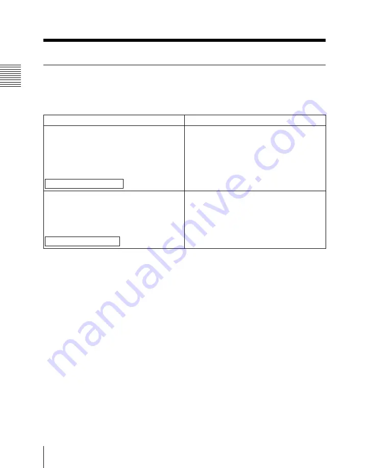
SETUP DATA Menu Item List

This section explains the items in the SETUP DATA menu.

SYSTEM CONFIG settings

Scratchpad display

Status display

AUX | P3 = AUX (P3)

When a VTR is connected to the AUX/PLAYER-3
connector, specifies whether to control that VTR
as player 3.

AUX: Do not control as player 3.

P3: Control as player 3.

Factory default setting: AUX

SETUP DATA

SYSTEM CONFIG.

[AUX/P3] KEY SELECT

=AUX (P3)

BEEP = ON (OFF)

Specifies whether a beep sounds from the control
panel on errors and for certain operations.

ON: Beep sounds.

OFF: Beep does not sound.

Factory default setting: ON

SETUP DATA

SYSTEM CONFIG.

BEEP SELECT

=ON (OFF)

SETUP DATA Menu

(Continued)

Summary of Contents for BVE-700

Page 1: ...Software Version 1 10 English Manual to be supplemented BVE 700 User s Guide 1st Edition Software Version 1 00 and Later Printed in Japan 2000 08 13 2000 BVE 700 SY 3 205 042 01 1 Sony Corporation Communication System Solutions Network Company ...

Page 2: ...itional functions and changes in Version 1 10 of the BVE 700 Use the pages of this supplement to replace the corresponding pages in your copy of the User s Guide Pages which are not present in the existing User s Guide are additions ...

Page 3: ... 2 EXT KEY button 3 MATTE button Inserts or removes a title key 1 TITLE T TRNS button TITLE Press this button lighting it to superimpose a key signal title text signal on the video Press this button again turning it off to remove the superimposed title T TRNS title transition SHIFT TITLE Press this button to insert or remove a superimposed title over a preset transition time To set the transition ...

Page 4: ...ou that you can use knobs 1 LUM 2 SAT and 3 HUE to adjust the color of the title text 8 PATTERN EDGE section 1 BORDER button PATTERN EDGE BORDER SOFT REV 2 SOFT button 3 REV button Sets and adjusts wipe pattern edges Also sets the wipe direction 1 BORDER button Press this button lighting it to attach a border to the boundary of a wipe pattern You can adjust the color and width of the border with t...

Page 5: ... start point wipe pattern number etc Data for the VTRs currently selected in the PLAYER control section and RECORDER PLAYER control section flashes You can use the numeric keypad buttons to modify it When no data has been set is displayed Drop frame mode timecode is displayed with a dot to the lower right of the first digit in the minutes position When timecode has been calculated automatically a ...

Page 6: ...splays the OUT points for each VTR Pressing this button while holding down the CTRL button allows you to set preroll times directly from the numeric keypad without using a menu 5 EFF effect button Displays the effect wipe dissolve start point in the R VTR time counter display panel At the same time displays the OUT point of the player selected in the A row of the SOURCE section see page 1 6 and th...

Page 7: ...from the start to the end of an effect in the R VTR time counter display panel EDIT NO edit number SHIFT TRANS TIME Press this button lighting it to display the 4 digit edit number of the current edit in the R VTR time counter display panel In this state entering another number loads the corresponding edit from EDL memory Depending on the state of the edit an n new edit r recorded edit or d delete...

Page 8: ...ressed Pressing a button again cancels the channel selection 2 A5 to A8 indicators Light to show that channels A5 to A8 are selected for audio insert editing 3 V CHG BAS button V video insert Press this button lighting it to conduct video insert editing CHG BAS change base SHIFT V Specifies whether to use the video IN point or audio IN point as the base point in insert editing using both video and...

Page 9: ...s to light the TC indicators If there is no timecode recorded on even one of the tapes press the MODE buttons to light the CTL indicators TC indicator CTL indicator TC indicator CTL indicator TC indicator CTL indicator SETUP SHIFT DISS button Press the button to put the system into setup mode and make basic system settings and initial edit condition settings For details see Chapter 6 Setup MIXER b...

Page 10: ...e figure below appears when you press the STATUS SHIFT EFF OUT button in the MON OUT section of the control panel IN IN point data OUT OUT point data EFFECT Effect start point SPLIT Split edit data DURATION Duration SHOW START Edit start point P1 P2 P3 R TOTAL Total edit time SPEED Playback speed T TIME Title transition time PTTRN NO Wipe pattern number REEL Reel number TRANS TIME Transition time ...

Page 11: ... button stops flashing and lights 3 The recorder and player begin to run from the preroll point and an assemble edit is executed For the rest of the procedure you can proceed in the same way as when performing a normal assemble edit To use an internal VTR signal as the first edit video signal Execute the first edit after selecting VTR SG in the setup menu INITDATA 1EDVSRC and INITDATA 1EDASRC Note...

Page 12: ...he difference between the video IN point and the audio IN point is called the split offset The maximum split offset is 59 seconds and 29 frames Note Split edit points can be set only on the recorder or the player selected in the A row of the SOURCE section This section provides an example that shows how to set the IN point for a split edit based on audio the OUT point can be set in the same way as...

Page 13: ...ain monitor Press the EFF OUT button in the MON OUT section lighting it To superimpose a title key instantly Proceed as follows Inserting Titles Title Key TITLE KEY indicator A B SOURCE TYPE TITLE PATTERN EDGE REMOTE MON OUT COL BAR BKGD BLACK LUM WIDTH CLIP SAT SOFT GAIN HUE FADER AUDIO BASE DENSITY NEW EDIT 2 1 Continued Button states Signals used in title key Key fill signal Same as key source ...

Page 14: ...o adjust the density of the characters rotate knob 3 DENSITY To remove the superimposed title Press the TITLE button again turning it off The superimposed title disappears instantly To fade in a title over a specified period Instead of superimposing the title instantly you can fade it in over a specified period transition time Proceed as follows A B SOURCE PLAYER WIPE PATTERN ENTRY EDIT MODE A5 A6...

Page 15: ...t DFS 700 or HDS DVS In the SETUP DATA SW ER CONFIG CROSS POINT menu specify the cross points corresponding to the BVE 700 sources DFS 700 700P settings If you are using the DFS 700 700P select PVE 500 in the SETUP PORTS menu of the DFS 700 700P This allows the BVE 700 and the DFS 700 700P to communicate over the serial interface This interface is enabled when the GPI button on the control panel o...

Page 16: ......

Page 17: ... of the currently connected VTR does not agree with the reel name specified in the edit that you have loaded The error message UNMOUNTED REEL appears Insert the correct reel cassette To record an edit after loading it auto assembly With the edit loaded from the EDL press the REC button The edit and the following edits in the EDL are recorded Note Edits with REC marks r indicating that they have al...

Page 18: ...t with an edit number 1 larger Press the FS SHIFT button Press the button again to load the edit with the next larger edit number Each press of the button loads the edit with the next number If the current edit is a new edit pressing the FS SHIFT button registers the current edit and puts the system into new edit creation mode so that you can create another new edit To return from a loaded edit to...

Page 19: ... if the BEEP item is set to ON in the setup menu SETUP DATA SYSTEM CONFIG Note After targeting a group of edits for deletion you cannot specify that one or more edits in the group be deleted and the rest saved All targeted edits are deleted whenever you perform the above operation To delete all edits in the EDL with a simple button operation Note Unlike deletions made with the INIT DATA menu this ...

Page 20: ...ust as it is Loading EDL data from external devices You can load EDL data created on external devices into the BVE 700 s EDL memory over the RS 232C interface This data can be used and modified in exactly the same way as EDL data created on the BVE 700 EDL format The BVE 700 uses the BVE 9100 EDL format RS 232C interface configuration The RS 232C interface must be configured to match the device co...

Page 21: ...IRECT DMC DIAL SHTL DIAL WIPE 10 R REC KEY BAUD FORMAT SNAP OUT MON MODE PVW MODE CUEUP XPT RS 232 PARAMETER VIDEO MODE VTR STATUS TOTAL TIME ERROR MSG PARITY CHECK LENGTH STOP BIT Level 0 Level 1 Level 2 Level 3 Level 4 Page 6 10 Page 6 10 Page 6 11 Page 6 11 Page 6 12 Page 6 12 Page 6 12 Page 6 13 Page 6 13 Page 6 13 Page 6 13 Page 6 14 Page 6 14 Page 6 14 Page 6 15 Page 6 15 Page 6 16 Page 6 17...

Page 22: ...3 VTR C BLOCK 1 BLOCK 2 BLOCK 3 AUDIO EDIT MODE BLOCK 1 3 BLOCK 1 3 BLOCK 1 3 BYTE 1 8 BYTE 1 8 BYTE 1 8 BYTE 1 8 BYTE 1 8 BYTE 1 8 AUDIO MODE MIXER CONFIG VTR PORT SETUP Level 0 Level 1 Level 2 Level 3 Level 4 Continued Page 6 18 Page 6 21 Page 6 21 Page 6 21 Page 6 22 Page 6 23 Page 6 23 Page 6 24 Page 6 24 Continued SETUP DATA Menu Page 6 25 ...

Page 23: ... DELAY P1 IN DELAY P2 IN DELAY P3 IN DELAY OUT DELAY DATE TIME YEAR MONTH DATE CLOCK SET DEFAULT Level 0 Level 1 Level 2 Level 3 Level 4 Continued Page 6 34 Page 6 34 Page 6 34 Page 6 34 Page 6 35 Page 6 35 Page 6 35 Page 6 35 Page 6 36 ...

Page 24: ...nnector specifies whether to control that VTR as player 3 AUX Do not control as player 3 P3 Control as player 3 Factory default setting AUX SETUP DATA SYSTEM CONFIG AUX P3 KEY SELECT AUX P3 BEEP ON OFF Specifies whether a beep sounds from the control panel on errors and for certain operations ON Beep sounds OFF Beep does not sound Factory default setting ON SETUP DATA SYSTEM CONFIG BEEP SELECT ON ...

Page 25: ...ttons when the system is not in data loading or entry mode WIPE Use as wipe pattern buttons 10 Use as numeric buttons Factory default setting 10 SETUP DATA SYSTEM CONFIG WIPE 10 KEY SELECT 10 WIPE R REC KEY OFF ON Specifies whether to enable the R VTR R REC button in the RECORDER PLAYER section of the control panel ON Enable the R VTR R REC button OFF Disable the R VTR R REC button Factory default...

Page 26: ...E Disables parity check ODD Sets parity check to odd EVEN Sets parity check to even Factory default setting DISABLE When you make a setting by pressing the ENTER button the system automatically enters the mode in which you can set the next item LENGTH LENGTH 8 BITS 7 BITS Sets the data length 7 BITS Sets the data length to 7 bits 8 BITS Sets the data length to 8 bits Factory default setting 8 BITS...

Page 27: ...rder and EFF OUT and the USED BANK selects the cross point of the selected device FULL During previews transitions between recorder and source video are done with the USED BANK The USED AUX BUS selects the EFF OUT and the USED BANK switches between the recorder and source When FULL is specified the optional BKE 701 HD Switcher Board operates in the same way as when MON is specified Factory default...

Page 28: ... type of video switcher Select the switcher in your system BKE 701 Specifies control of the BKE 701 HDS DVS Specifies control of the HDS 7000 and compatible DFS 700 Specifies control of the DFS 700 series Factory default setting BKE 701 SETUP DATA SWITCHER CONFIG SWITCHER TYPE BKE 701 HDS DVS DFS 700 SETUP DATA Menu Continued ...

Page 29: ...Chapter 6 Setup 6 19 6 Setup ...

Page 30: ...6 20 Chapter 6 Setup 6 Setup ...

Page 31: ... is done at the recorder monitor The monitor switches between the recorder and LINE OUT and LINE selects the cross point of the selected device FULL During previews and recording transitions between recorder and source audio is done by LINE The monitor select LINE OUT and LINE switches between the recorder and the source Factory default setting MON SETUP DATA AUDIO MODE PREVIEW MODE MON EE FULL CU...

Page 32: ...2CH SRC P1 00 to 63 SRC P2 00 to 63 SRC R VTR 00 to 63 Establishes correspondences between each of the sources and audio mixer cross points Select sources with the VTR selection buttons in the PLAYER control section or the RECORDER PLAYER control section Enter setting values with the numeric keypad A setting is cancelled if you operate any of the VTR selection buttons before confirming the setting...

Page 33: ...n about each item SIGNAL FORMAT BKE 701 SETUP OUTPUT FORMAT SCREEN W CLIP D CLIP H ADJUST V ADJUST EDGE SOFT COLOR LIMIT LUM MAX LUM MIN TYPE SOURCE FILL WIPE MATTE TITLE DEFAULT Page 6 38 Page 6 38 Page 6 39 Page 6 39 Page 6 39 Page 6 40 Page 6 40 Page 6 41 Page 6 41 Page 6 41 Page 6 41 Page 6 41 Page 6 41 2 Level 0 Level 1 Level 2 Page 6 41 2 ...

Page 34: ... number of effective scanning lines 1080 1080 effective scanning lines 1035 1035 effective scanning lines Factory default setting 1080 BKE 701 SETUP SIGNAL FORMAT FORMAT 1080 1035 SCREEN 16 9 4 3 Specifies the screen format 16 9 The screen format is 16 9 4 3 The screen format is 4 3 Factory default setting 16 9 Scratchpad display Status display BKE 701 SETUP SIGNAL FORMAT SCREEN 16 9 4 3 ...

Page 35: ...nce level is 7 Factory default setting 0 BKE 701 SETUP MATTE MINIMUM LUM LEVEL 0 7 TYPE LUMINANCE LINEAR Specifies the key type LUMINANCE Use a luminance key as the key type LINEAR Use a linear key as the key type Factory default setting LUMINANCE Scratchpad display Status display BKE 701 SETUP TITLE TYPE LUMINANCE LINEAR SOURCE P3 AUX P1 P2 TITLE Specifies the key source signal P1 Use the signal ...

Page 36: ...s the key fill signal P1 Use the signal input to the PLAYER 1 connector as the key fill signal P2 Use the signal input to the PLAYER 2 connector as the key fill signal P3 AUX Use the signal input to the AUX PLAYER 3 connector as the key fill signal TITLE Use the signal input to the TITLE connector as the key fill signal Factory default setting TITLE Scratchpad display Status display BKE 701 SETUP ...

Page 37: ......

Page 38: ...OAD SHIFT 0 button in INIT DATA mode BKE 701 SETUP LOAD Scratchpad display Status display STORE 701 USR1 2 3 4 Stores up to 4 sets of BKE 701 SETUP data in 4 independent user areas SETUP USR1 to SETUP USR4 To store setup data press the STORE CTRL F TC button in BKE 701 SETUP mode to display STORE 701 USR1 Select the user area by pressing the ALL STOP button and confirm by pressing the ENTER button...

Page 39: ... PULSE PULSE WIDTH REACTION TIME GPI 1 TIMING GPI 2 TIMING GPI 3 TIMING GPI 4 TIMING DURING PREVIEW GPI 1 WIDTH GPI 2 WIDTH GPI 3 WIDTH GPI 4 WIDTH GPI 1 REACT GPI 2 REACT GPI 3 REACT GPI 4 REACT GPI PVW INIT DATA Menu Page 6 45 Page 6 46 Page 6 46 2 Page 6 46 2 Page 6 47 Page 6 47 Page 6 48 Page 6 48 Continued Level 0 Level 1 Level 2 Level 3 Page 6 49 Page 6 49 Page 6 49 Page 6 49 Page 6 49 Page ...

Page 40: ...PI 1 TEST FIRE GPI 2 TEST FIRE GPI 3 TEST FIRE GPI 4 TEST FIRE DEC BASE CHANGE BASE MODE OVERFLOW EDIT SKIP REC REC MARK CLEAR BUTT EDIT PRE READ EDL CLEAR Page 6 51 Page 6 51 Page 6 51 Page 6 51 Page 6 51 Page 6 51 2 Page 6 52 Page 6 52 Page 6 52 Page 6 52 Page 6 52 Page 6 53 Page 6 53 Continued ...

Page 41: ... SHOW START TIME Factory default setting UNDEFINED Enter a value with the numeric keypad and confirm by pressing the ENTER button If less than 8 digits have been input when the ENTER button is pressed the most significant digits of the 8 digit value are set to 0 If you press the ENTER button with nothing displayed in the scratchpad the message STRT UNDEFINED appears and no setting is made If you d...

Page 42: ... the cross point set for a color bar signal BKGD When BKE 701 used Sets the source signal to a color bar signal LUM SAT and HUE follow the settings in force at the time of the first edit When external switcher used Sets to the cross point set for a color background signal VTR SG Sets the source signal to a signal generated by the internal signal generator of the VTR When this setting is made and t...

Page 43: ...ng fewer than 8 digits the system automatically supplies 0 in the most significant places Pressing the 3 C button changes the setting to undefined An undefined setting is not an error Scratchpad display Status display INIT DATA USERS BIT 00 00 00 00 to FF FF FF FF Scratchpad display Status display 1EDASRC MUTE VTR SG Specifies the audio signal to use in first edits MUTE Mute VTR SG Sets the audio ...

Page 44: ......

Page 45: ...he value is not set in case of an error To set the preroll time with button operations only Press the CTRL IN buttons enter the desired preroll time from the numeric keypad and press the ENTER button Scratchpad display Status display INIT DATA PREROLL TIME SS FF PST ss ff absolute value input ss ff ss ff relative value input Sets the postroll time which determines how far VTRs run past their OUT p...

Page 46: ...or the recorder and players in automatic editing the recorder s setting takes priority DF Drop Frame mode NDF Non drop frame mode Factory default setting DF INIT DATA FRAME CONTROL MODE DF NDF Scratchpad display Status display CTL DISP 9 14 00 24 Selects the display positions for CTL display mode 9 14 Display CTL at 9 59 59 29 to 14 00 00 00 00 24 Display CTL at 00 00 00 00 to 23 59 59 29 Factory ...

Page 47: ... Scratchpad display Status display INIT DATA GPI PULSE TEST FIRE GPI 1 GPI 2 GPI 3 GPI 4 indicates the currently selected GPI port Scratchpad display Status display DEC BASE VIDEO AUDIO Specifies whether to use the video signal or the audio signal as the base signal for edit timing in split editing This setting can be changed as required at the time of the edit VIDEO Use video as the decision base...

Page 48: ...udio delay 2 00 Video Audio base Video advance 2 00 Scratchpad display Status display O FLOW O WRITE INHIBIT Specifies what to do when an attempt is made to register new edit data when EDL memory is full O WRITE Register the new edit data after deleting existing data beginning with the data with the smallest edit data number INHIBIT Do not register the new edit data A beep tone sounds and the erro...

Page 49: ......

Page 50: ...nsult REC marks during Auto Assembly OFF Do not consult REC marks during Auto Assembly Factory default setting ON INIT DATA REC MARK ON OFF BUTT EDIT OFF ON Specifies whether to use the butt edit function which allows you to execute edits without setting IN points ON Use the butt edit function OFF Do not use the butt edit function Factory default setting OFF Scratchpad display Status display INIT ...

Page 51: ...ined below to set a VTR constant VTR CONST USRnn nn 01 to 10 Selects a VTR number Select by pressing the ALL STOP button and confirm by pressing the ENTER button The system automatically moves on to selection of the next step block number selection USR nn BLOCK n n 1 to 3 Selects a block number Select by pressing the ALL STOP button and confirm by pressing the ENTER button The system automatically...

Page 52: ...R proceed as follows 1 Select a user VTR constant number and press the selection button for the desired VTR The following message appears in the scratchpad COPY XXX CONST XXX is the name of the selected VTR 2 Press the ENTER button to execute the copy or the RETURN button to cancel the copy VTR CONSTANT Menu ...

Page 53: ......

Page 54: ... in the INFORMATION menu SYSTEM REFERENCE MODE information MAIN SOFT VERSION information PANEL SOFT VERSION information INFORMATION Menu Level 0 Level 1 Scratchpad display Status display REF 1125 59 94 Displays the reference signal in current use Factory default setting 1125 59 94 INFORMATION REF xxxx Scratchpad display Status display MAIN xxxxxxxxxx Displays the version of the main application IN...

Page 55: ...he boot ROM in the processor unit INFORMATION BOOT xxxxxxxx Scratchpad display Status display CKG BOARD ID xx Displays the ID of the CKG board INFORMATION CKG BOARD ID xx Scratchpad display Status display IO BOARD ID xx Displays the ID of the IO board INFORMATION IO BOARD ID xx Scratchpad display Status display MIX BOARD ID xx Displays the ID of the MIX board INFORMATION MIX BOARD ID xx http getMA...

Page 56: ...ceed to step 3 3 Press the CTRL F TC buttons to specify the storage block The current storage block appears in the scratchpad Example STORE BLOCK USR1 4 Press the ALL STOP button to switch between the four storage blocks as required Switching order STORE BLOCK USR1 STORE BLOCK USR2 STORE BLOCK USR3 STORE BLOCK USR4 5 Press the ENTER key when the desired storage block appears in the scratchpad The ...

Page 57: ...o step 3 3 Press the CTRL REC buttons to specify the storage block The current storage block appears in the scratchpad Example RESTORE BLOCK USR1 4 Press the ALL STOP button to switch between the four storage blocks as required Example RESTORE BLK USR1 RESTORE BLK USR2 RESTORE BLK USR3 RESTORE BLK USR4 5 Press the ENTER key when the desired storage block appears in the scratchpad The current setup...

Page 58: ...the menus stay on the current level and proceed to step 3 3 Prepare the dump destination device and press the DUMP Shift 00 button when it is ready The current menu data is dumped to the device To load setup menus Proceed as follows 1 Press the SETUP SHIFT DISS button to put the system into setup mode 2 To load an individual menu navigate to that menu To load all of the menus stay on the current l...

Page 59: ...when the Pn TC JUMP item in the AUX DATA menu is set to ON UNMOUNTED REEL S UNMOUNTED REEL M UNMOUNTED REEL There is no reel mounted on the VTR or the reel name specified for the current edit does not match the reel name of the tape in the connected VTR Mount the correct reel in the VTR VTR NOT READY S VTR NOT READY T Err CntrL for affected VTR M VTR NOT READY VTR is not connected Connect the VTR ...

Page 60: ...trols in the parameter adjustment section of the control panel 2 Press the BORDER button lighting it if you want to add a border to the mosaic area Press the SOFT button lighting it if you want the mosaic area to have soft edges A B SOURCE PLAYER WIPE PATTERN ENTRY EDIT MODE A5 A6 RECORDER PLAYER TYPE TITLE PATTERN EDGE REMOTE MON OUT A7 A8 P1 P2 P3 RPLAY REC PVW RPLY COL BAR BKGD BLACK LUM WIDTH ...

Page 61: ... Indicator Adjustment knobs Cell CTRL SELECT BKGD blinks 1 Cell aspect ratio adjustment 3 Cell size Region CTRL SELECT EDGE WIDTH blinks 1 Region aspect ratio adjustment 2 Edge softness 3 Region size Position CTRL SELECT EDGE MATTE blinks 1 Horizontal position 2 Vertical position 3 Region size Border SELECT EDGE WIDTH lights 1 Border width 2 Edge softness 3 Region size Border color SELECT EDGE MAT...

Page 62: ...the SOURCE section and the MATTE button in the TITLE section The selected button lights A B SOURCE PLAYER WIPE PATTERN ENTRY EDIT MODE A5 A6 RECORDER PLAYER TYPE TITLE PATTERN EDGE REMOTE MON OUT A7 A8 P1 P2 P3 RPLAY REC PVW RPLY COL BAR BKGD BLACK LUM WIDTH CLIP SAT SOFT GAIN HUE FADER AUDIO BASE DENSITY NEW EDIT 1 6 5 2 4 3 Button Selected signal P1 Signal input to the PLAYER 1 connector P2 Sign...

Page 63: ... you have applied Press the CLEAR button and then press the CTRL SWER button Button Function P1 Turns on and off for the signal input to the PLAYER 1 connector P2 Turns on and off for the signal input to the PLAYER 2 connector AUX P3 Turns on and off for the signal input to the AUX P3 connector R VTR Turns on and off for the signal input to the RECORDER connector MATTE Turns on and off for the sig...

Page 64: ...A 10 Appendix Appendix Wipe Patterns Standard Wipes 1 2 3 4 5 6 7 8 9 10 11 12 13 14 15 16 17 18 19 20 21 22 23 24 26 ...

Reviews: