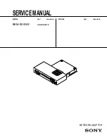
background image

1-6

BKM-B30NW

10 

(GB)

Setting Up the Display (Network Adaptor)

Basic setups such as IP address and wireless LAN
settings are necessary for networking operations of the
Display (Network Adaptor). You can set them up
either from the Display (Network Adaptor) or a
computer connected to the same LAN.

Before setting up

• Attach the Network Adaptor to the PFM-42B1.
• Turn on the Display with the 

#

1

 key on the Remote

Commander supplied with the PFM-42B1 or control
panel of the Display.

• Press the OPTION key on the Remote Commander to

set the input to INPUT 3 PC.  The Start up Window is
displayed.

• When you set up from the Display, operate with the

supplied mouse and keyboard or connected keyboard.

For information on the screen keyboard, see page 31 (GB).

• After the above preparations, turn on the computer

from which you set up the Display.

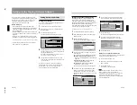
Setting Up from the Display

Setting the password

You can set a password for protection against access
from remote network users.

1

Click Desktop View in the Start up window.

2

From the Start menu, click Control Panel in the
Desktop window.

3

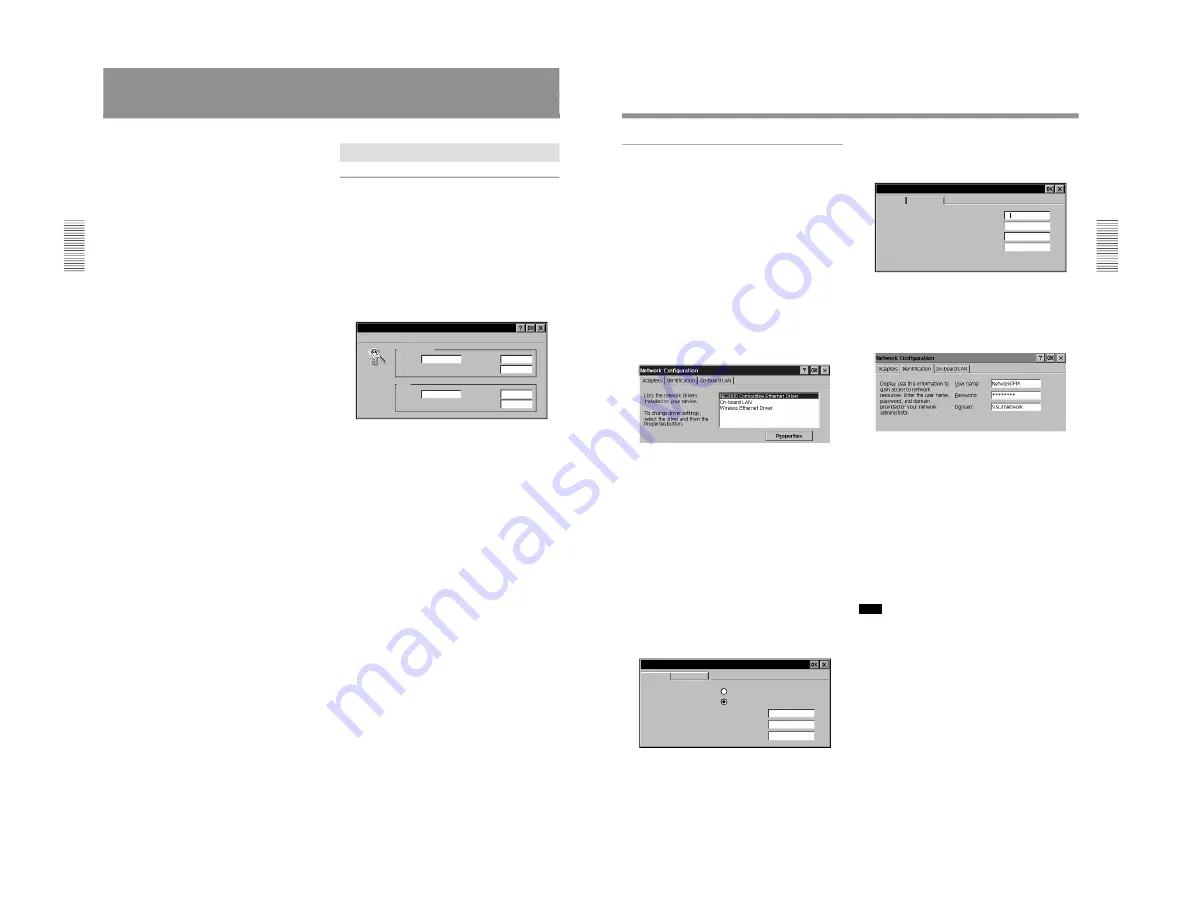
Double-click the Password icon.
The Password Properties dialog box appears.

Password Properties

Administrator

Name:

_

root

Password:

_

I

Confirm password:

_

User

Name:

_

Password:

_

Confirm password:

_

4

  Specify the Password for Administrator, then enter

the same password again in the Confirm password
text box for Administrator.
The Name of Administrator is preset as “root” at
the factory. It cannot be changed.

5

  Specify the Name and Password for User, then

enter the same password in the Confirm password
text box for User.

When you are required to enter the password for
Administrator or User while you are operating the
Display from a computer, enter the Name and
Password which you set in steps 

4

 and 

5

.

11 

(GB)

Setting up the network configuration

Setting up the network configuration, such as IP
address setting, is necessary for building a LAN
connection. The IP address of the Display (Network
Adaptor) will be displayed on the task bar of the Start
up and the Desktop windows of the Display.
If the connection environment is changed, you need to
set up the network configuration again.

For details, contact your network administrator.

1

Click Desktop View in the Start up window.

2

From the Start menu, click Control Panel in the
Desktop window.

3

Double-click the Network icon.
The Network Configuration dialog box appears.

4

Select the driver name according to the network
connection type.
You can select one of the following driver names.
NE2000 Compatible Ethernet Driver: When

using the recommended NE2000 compatible PC
LAN card.

Wireless Ethernet Driver: When using the

specified wireless LAN PC card.

On-board LAN: When using the ETHER

connector to connect to LAN.

The selected driver’s setting dialog box appears.

5

Confirm that the “Specify an IP address” radio
button is selected, and set the necessary items.
The IP Address is initially set to “192.168.0.1,”
and the Subnet Mask is set to “255.255.0.0” at the
factory.

'Wireless Ethernet Driver' settings

IP Address

1 9 2 . 1 6 8 .   0   .   1

2 5 5 . 2 5 5 .   0   .   0

.

.    

.  

An IP address can be
automatically assigned to this
computer. If your network
does not automatically assign
IP addresses, ask your network
administrator for an address,
and then type it in the space
provided.

Name Servers

Obtain an IP address via DHCP

Specify an IP address

IP Address:

Subnet Mask:

Default Gateway:

_

_

_

_

_

6

Click the Name Servers tab to display the Name
Servers dialog box, then set the necessary items.

'Wireless Ethernet Driver' settings

IP Address

.

.    

.  

.

.    

.  

.

.    

.  

.

.    

.  

Name server addresses may be
automatically assigned if DHCP
is enabled on this adapter.
You can specify additional
WINS or DNS resolvers in the
space provided.

Name Servers

Primary DNS:

Secondary DNS:

Primary WINS:

Secondary WINS:

_

_

_

_

7

Click the OK button.
The Network Configuration dialog box reappears.

8

According to your requirements, click the
Identification tab and set the necessary items.

9

Click the OK button.

When you use a wireless LAN PC card

If you select Wireless Ethernet Driver in step 

4

, follow

the steps below after performing step 

7

.

1

Click the On-board LAN tab.

2

Remove the check from the “Enable On-board
LAN” checkbox.

3

Click the OK button.
The window in step 

3

 reappears.

Note

Once the On-board LAN was deactivated, it is not
shown in the driver names of the Network
Configuration dialog box. If you want to select On-
board LAN, check the Enable On-board LAN
checkbox, then repeat from step 

3

 in “Setting up the

network configuration.”

Summary of Contents for BKM-B30NW

Page 1: ... SERVICE MANUAL NETWORK ADAPTOR BKM B30NW US CND AEP E MODEL DEST CHASSIS NO MODEL DEST CHASSIS NO ...

Page 2: ...ie Gefahr eines elektrischen Schlages Feuergefahr und Verletzungen zu vermeiden sind bei Wartungsarbeiten strikt die Angaben in der Anleitung zu befolgen Andere als die angegeben Wartungsarbeiten dürfen nur von Personen ausgeführt werden die eine spezielle Befähigung dazu besitzen AVERTISSEMENT Ce manual est destiné uniquement aux personnes compétentes en charge de l entretien Afin de réduire les ...

Page 3: ... constructeur Mettre au rebut les batteries usagées conformément aux instructions du fabricant ADVARSEL Lithiumbatteri Eksplosionsfare ved fejlagtig håndtering Udskiftning må kun ske med batteri af samme fabrikat og type Levér det brugte batteri tilbage til leverandøren ADVARSEL Lithiumbatteri Eksplosjonsfare Ved utskifting benyttes kun batteri som anbefalt av apparatfabrikanten Brukt batteri retu...

Page 4: ...therlands Voor de klanten in Nederland Dit apparaat bevat een MnO2 Li batterij voor memory back up Raadpleeg de instructies deze handleiding voor het verwijderen van de batterijen NL Gooi de batterij niet weg maar lever hem in als KCA 2 P ...

Page 5: ...24 2 Service Informations 2 1 Board Layout 2 1 2 2 Disassembly 2 2 2 2 1 QN Board Removal 2 2 2 2 2 Main Parts Removal on the QN Board 2 3 2 2 3 BKM B30NW Tool for Writing Software 2 4 3 Spare Parts 3 1 Notes on Repair Parts 3 1 3 2 Exploded Views 3 2 3 3 Electrical Parts List 3 4 3 4 Miscellaneous 3 7 3 5 Packing Materials Supplied Accessories 3 7 1 ...

Page 6: ......

Page 7: ...M B30NW Section 1 Operating Instructions Reprinted from the operating instructions 2001 Sony Corporation BKM B30NW 4 085 252 01 1 BKM B30NW Network Adaptor Operating Instructions GB 1 1 Operating Instructions ...

Page 8: ... 680 Kinderkamack Road Oradell NJ 07649 U S A Telephone No 201 930 6972 Reorient or relocate the receiving antenna Increase the separation between the equipment and receiver Connect the equipment into an outlet on a circuit different from that to which the receiver is connected Consult the dealer or an experienced radio TV technician for help You are cautioned that any changes or modifications not...

Page 9: ...ely The functions allow you to run a slide show using a PowerPoint file or to project an Excel file without any conversion Image Viewer Function The Network Adaptor has built in Image Viewer function allowing you to view images created in the JPEG BMP GIF or PNG format to set up a slide show and to run a slide show using the images For installing the network adaptor to the Display please consult q...

Page 10: ...ct the mouse Notes You cannot connect equipment other than the mouse to this connector Connect the mouse before the power of the Display is turned on 1 2 3 4 5 7 GB You can connect to the LAN with the LAN cable 10 100BASE T or wireless LAN by attaching the wireless LAN PC card You can also use the memory card This section describes the tasks that are required for using the networking function of t...

Page 11: ...liant Display Network Adaptor Computer Wireless LAN PC card recommended IEEE802 11b compliant PC memory card Type II Display Network Adaptor PC CARD slot Preparations for Using the Networking Function PC CARD slot 9 GB Using the PC Card The PC CARD slot on the Network Adaptor accepts one PCMCIA Type II PC card To connect to a LAN it is required to insert the specified recommended LAN PC card or wi...

Page 12: ...nfiguration again For details contact your network administrator 1 Click Desktop View in the Start up window 2 From the Start menu click Control Panel in the Desktop window 3 Double click the Network icon The Network Configuration dialog box appears 4 Select the driver name according to the network connection type You can select one of the following driver names NE2000 Compatible Ethernet Driver W...

Page 13: ...tween the Display Network Adaptor and computers without using the wireless LAN access point follow the steps below on the Display Network Adaptor only 1 Follow steps 1 to 5 in Using the wireless LAN access point In the Access Point settings dialog box set the Nickname of this mode 2 Click the checkbox next to Peer to Peer 3 Enter an optional Access Point ID You can type up to 32 alphanumeric chara...

Page 14: ...he setup window 1 Start the computer s browser software Internet Explorer 4 0 or later versions or Netscape Navigator 4 5x or 4 7x version 2 Type http xxx xxx xxx xxx for the IP address of the Display setup If the IP address is not changed from the factory preset one type http 192 168 0 1 setup when using a LAN PC card or http 192 168 0 2 setup when using the ETHER connector If the number of the I...

Page 15: ...play on the Display page 25 Select where the file is stored the computer or Display then select the Excel file you want The Worksheet Viewer starts Displaying an Excel file 17 GB Displaying an image onto the Display using a file stored in a computer You can display an image on the Display by operating from a computer Displaying an image or running a slide show on the Display using a file store in ...

Page 16: ...file Slide Viewer starts and the selected file appears in slide view Setting up a slide show page 33 Set which slides to use and how to advance a slide in a slide show Running a slide show 19 GB Running a presentation using a file stored in the Display Network Adaptor or memory card By using a PowerPoint file stored in the Display or in the PC memory card you can run a presentation by operating th...

Page 17: ...age files 4 PRESENTATION VIEWER icon Opens the select window for starting the PowerPoint viewer Slide Viewer or Excel viewer Worksheet Viewer 5 Help Resting the pointer over each item displays the instructions for the item This makes your operations easier in each window 6 Input select menu Select the input to the Display 7 Aspect ratio select memu Sets the aspect ratio of the picture Preparations...

Page 18: ...will be stored when you click the Set Up or View button Note When you delete a file using File Manager entering the password is not required even if the password is set for the file BACK button Click to return to the previous window Password setting box HOME button Click to return to the Application Select window 23 GB When you select FLAT DISPLAY in step 2 The file list showing the files stored i...

Page 19: ...es not support some Excel features such as a split feature Displaying an Excel file 1 Follow steps 1 to 3 in Running a Presentation Using the Slide Viewer Running a presentation on page 22 GB Make sure to select an Excel file xls file in step 3 2 Click the View button The Worksheet Viewer starts A worksheet of the selected file is displayed on the Display You can zoom in or out the worksheet displ...

Page 20: ...due to lack of memory In this case reduce the image to obtain a smaller file size 5 Scroll buttons Clicking the arrows changes the display area of the image on the screen if the enlarged image does not fit the screen 6 END button Ends or suspends the full screen display to return to the File Select window 7 HOME button Returns to the Application Select window 27 GB Note When you exit the Image Vie...

Page 21: ...w The File Manager window appears and the list of files stored in the Display Network Adaptor pops up 2 Select the file you want to delete You can check all the files you want to delete 3 Click the Delete button All the files you have checked are removed from the file list Note You can delete a file even if the password is set for the file 29 GB Controlling the Display from a Computer You can perf...

Page 22: ... Commander to set the input to INPUT 3 PC After displaying the SONY mark the Start up window is opened Opening the Desktop window Click Desktop View Names and functions of the Desktop window 1 My Display icon Browses the folders in the Display Double clicking the icon shows the Memory card icon etc 2 Internet Browser icon Double clicking the icon connects to the Internet 3 Presentation Viewer icon...

Page 23: ...ed file Indicates version information on the program Shows a slide in Slide View mode Shows a slide in Note View mode Runs a slide show Runs a slide show Sets up the slide show 33 GB 5 When you want to set up the slide show click Set Up Show from the View Show menu The Set Up Show dialog box opens For details see Help for Slide Viewer 6 Click Run from the View Show menu to run the slide show Using...

Page 24: ...or a memory card installed in the Display Network Adaptor then run a slide show by selecting the images you want When you start the Image Viewer of the Display Network Adaptor and select the folder which contains the files you want the main window opens About the main window of the Image Viewer 7 4 8 3 5 1 2 9 6 1 Help button Click to display the Help topic for the Image Viewer 2 Slide Clicking a ...

Page 25: ...ick the button on the tool bar The sub menu for choosing how to advance a slide opens Clicking one of the options starts a slide show Saving the slide show setting You can run a slide show repeatedly by using the files stored as the slide show setting files SHO files You can also change the settings of the stored setting files To save the file 1 Click Save from the Slide Show menu The Save Slide s...

Page 26: ...Manager then try to restart the slide show appears A slide show cannot be run The message File size is too large Decrease file size in any way for example by dividing it into smaller files then try to restart the slide show appears Internet Browser for the Display Network Adaptor cannot be started The message Password is set for the file Enter password appears The message You might have entered th...

Page 27: ...jack Composite video 1 Vp p 2 dB sync negative 75 ohms terminated PC CARD slot PC card slot Type II ETHER 10 100BASE T USB A type 2 General Dimensions 180 35 175 mm 71 8 17 16 7 inches w h d Mass Approx 580 g 1 lb 4 oz Power requirements DC 26 V 0 36 A lithium battery CR2032 for back up battery life approx 2 years Power consumption Approx 9 4 W Operating temperature 0 C to 35 C 32 F to 95 F Storag...

Page 28: ...1 22 BKM B30NW 4 085 253 01 1 Network Adaptor BKM B30NW Sony Corporation 2001 Printed in Japan Installation Manual for Dealers 1 2 Installation Manual for Dealers ...

Page 29: ...on the top and bottom of the installed adaptor or the panel cover Use a screwdriver to turn the screws counterclockwise Fig A 2 Remove the adaptor or the panel cover Fig A 3 Check the direction top bottom of the Network Adaptor and insert it into the Display Make sure that the connector inside the Display is firmly connected Fig B 4 Using a slot screwdriver tighten the two screws of the Network Ad...

Page 30: ...C power cord as illustrated How to attach the ferrite core 1 Attach the ferrite cores to both ends of the AC power cord and close the ferrite cores until they click 2 Wind the stopper round the cord so that the ferrite cores do not slide 3 Tighten the stopper and cut the surplus 1 2 3 4 085 583 01 1 BKM B30NW Sony Corporation 2001 Printed in Japan 1 3 About Ferrite Core ...

Page 31: ...2 1 BKM B30NW Section 2 Service Informations 2 1 Board Layout QN PC card assembly ...

Page 32: ... Two screws B2 6 x 5 1 Five screws B2 6 x 5 6 7 Five supports QN board DC fan Fan bracket 9 Shield plate Case assembly Case assembly Two screws B2 6 x 5 5 Two screws B2 6 x 5 4 Two screws PS2 6 x 10 0 One screw PS2 6 x 6 8 Front panel 2 3 CN4 Front cover ...

Page 33: ...r hexagon supports M3 2 Four screws P2 x12 6 Four nuts M2 TYPE2 7 PC card connector 8 Four screws P3 x4 3 4 PC card assembly 5 1 CN3 CN2 CN6 Removal of a lithium battery Lithium battery CR2032 Battery holder Remove a lithium battery toward in arrow direction Compact flash card ...

Page 34: ...in the compact flash 1 796 014 11 2 2 3 BKM B30NW Tool for Writing Software There is a tool for upgrading the software of the BKM B30NW Use this tool when upgrading the software in the Windows CE from the PC card slot The OC needs the open space of 32 Mbytes How to use 1 Copy this software to the PC card 2 Extract the software in the PC card When extracted a folder containing CEV file and the vers...

Page 35: ...tion the drive in which the compact flash card is inserted 5 Uncheck the CreateSerialBin and check the Over write 6 After entered press the MakeCF button Then the copy is started and the message Again appears when finished To continue copying press the OK If desired to finish press the Cancel C C Make CF v1 1 for Windows CE based Network Projedtor Source Destination Serial Number for VPL FE110 Num...

Page 36: ......

Page 37: ...ffer from those used for the unit These are because of parts common ality and improvement Parts list has the present standardized repair parts 3 Stock of Parts Parts marked with o at SP Supply Code column of the spare parts list may not be stocked Therefore the delivery date will be delayed 4 Harness Harnesses with no part number are not registered as spare parts In need of repair get components s...

Page 38: ...3 2 BKM B30NW Cover 3 2 Exploded Views 2 12 5 8 1 13 13 14 10 B2 6 x 5 M2 B2 6 x 5 B2 6 x 5 P2 x12 P3 x4 B2 6 x 5 PS2 6 x 6 PS2 6 x 10 E 3 0 CN4 P3 x4 2 9 7 11 6 3 4 ...

Page 39: ...1 815 229 11 o CONNECTOR 8 2 280 622 11 o SUPPORT M3 HEXAGON 9 3 612 399 01 o SUPPORT 10 4 076 108 01 o FINGER SHIELD 11 4 085 011 01 o CARD DUMMY 12 4 085 261 01 s COVER FRONT 13 4 085 343 01 o GASKET 14 4 085 344 01 o GASKET 7 621 255 75 s SCREW P 2X12 7 621 775 20 s SCREW B2 6X5 7 622 205 05 s NUT M2 TYPE2 7 624 106 04 s STOP RING 3 0 TYPE E 7 628 254 10 s SCREW PS 2 6X6 7 628 254 30 s SCREW PS...

Page 40: ...CH C52 1 164 156 11 s CAPACITOR CERAMIC 0 1MF 25V F QN BOARD Ref No or Q ty Part No SP Description C53 1 164 156 11 s CAPACITOR CERAMIC 0 1MF 25V F C54 1 164 156 11 s CAPACITOR CERAMIC 0 1MF 25V F C55 1 164 156 11 s CAPACITOR CERAMIC 0 1MF 25V F C56 1 164 156 11 s CAPACITOR CERAMIC 0 1MF 25V F C57 1 164 156 11 s CAPACITOR CERAMIC 0 1MF 25V F C58 1 115 566 11 s CAPACITOR CERAMIC 4 7MF B 6 3V C59 1 ...

Page 41: ...DIODE MA3100 TX D3 8 719 402 16 s DIODE MA3100 TX D4 8 719 402 16 s DIODE MA3100 TX D5 8 719 402 16 s DIODE MA3100 TX D6 8 719 402 16 s DIODE MA3100 TX D7 8 719 402 16 s DIODE MA3100 TX D8 8 719 078 81 s DIODE DF5A6 8FU TE85R DC1 1 476 876 11 s CONVERTER DC DC F1 1 533 922 21 s FUSE CHIP 1A QN BOARD Ref No or Q ty Part No SP Description FL1 1 239 899 21 s FILTER CHIP EMI FL2 1 239 899 21 s FILTER ...

Page 42: ...11 s RESISTOR CHIP 10K 1 16W 1608 R34 1 216 825 11 s RESISTOR CHIP 2 2K 1 16W 1608 R35 1 216 821 11 s RESISTOR CHIP 1 0K 1 16W 1608 R36 1 216 864 11 s CONDUCTOR CHIP 1608 R37 1 216 845 11 s RESISTOR CHIP 100K 1 16W 1608 R38 1 216 841 11 s RESISTOR CHIP 47K 1 16W 1608 R39 1 216 864 11 s CONDUCTOR CHIP 1608 R40 1 216 833 11 s RESISTOR CHIP 10K 1 16W 1608 R41 1 216 833 11 s RESISTOR CHIP 10K 1 16W 16...

Page 43: ...SE USB 2pcs 3 701 748 00 s HOLDER WIRE 1pc 4 085 252 01 o OPERATING INSTRUCTIONS JAPANESE ENGLISH FRANCH GERMAN SPANISH ITALIAN SIMPLIFIED CHINESE 1pc 4 085 253 01 o INSTALLATION MANUAL FOR DEALER JAPANESE ENGLISH FRANCH GERMAN SPANISH ITALIAN SIMPLIFIED CHINESE 1pc 4 085 583 01 o INSTRUCTION JAPANESE ENGLISH FRANCH GERMAN SPANISH ITALIAN SIMPLIFIED CHINESE 3 4 Miscellaneous 3 5 Packing Materials ...

Page 44: ......

Page 45: ...mercial leakage tester such as the Simpson 229 or RCA WT 540A Follow the manufacturers instructions to use these instruments 2 A battery operated AC milliammeter The Data Precision 245 digital multimeter is suitable for this job 3 Measuring the voltage drop across a resistor by means of a VOM or battery operated AC voltmeter The limit indication is 0 75 V so analog meters must have an accurate low...

Page 46: ...Sony Corporation B P Company 9 870 310 01 English 01GY22 1 Printed in Japan 2001 7 ...

Reviews: