DVS-7000AE IM
1-7
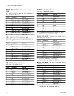
REMOTE 1
: RS-422A (D-sub 9-pin
.
Female)
<CONTROLLER>
(
*
1)
to External Device
Pin No.
Signal Name
Function
1
FG
Frame ground
2
RX-A
Received data (
_
)
3
TX-B
Transmitted data (
+
)
4
GND
Common ground
5
_
_
6
GND
Common ground
7
RX-B
Received data (
+
)
8
TX-A
Transmitted data (
_
)
9
_
_
REMOTE 2 to 5
(
*
2)
: RS-422A (D-sub 9-pin
.
Female)
<CONTROLLER>
(
*
1)
to External Device
Pin No.
Signal Name
Function
1
FG
Frame ground
2
RX-A
Received data (
_
)
3
TX-B
Transmitted data (
+
)
4
GND
Common ground
5
_
_
6
GND
Common ground
7
RX-B
Received data (
+
)
8
TX-A
Transmitted data (
_
)
9
_
_
(
*
2) : BKDS-7001(Option:IF-523 board) is in need of using the REMOTE
from 1 to 4.
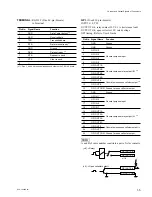
TERMINAL 1, 2
: RS-232C (D-sub 9-pin
.
Female)
to Terminal
Pin No.
Signal Name
Function
1
DCD
Data carrier detect
(
*
3)
2
RXD
Received data
3
TXD
Transmitted data
4
DTR
Data terminal ready
(
*
3)
5
GND
Ground
6
DSR
Data set ready
(
*
3)
7
RTS
Request to send
(
*
4)
8
CTS
Clear to send
(
*
4)
9
_
_
(
*
3) : Pins 1, 4 and 6 are short-circuited each other on the CN-1143 board.
(
*
4) : Pins 7 and 8 are short-circuitede each other on the CN-1143 board.
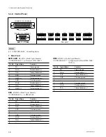
DISPLAY PANEL
: (D-sub 25-pin
.
Female)
to Display panel
Pin No. Signal Name
Function
1
GND
Ground
2
+
12 V
Power supply
+
12 V
3
SCLK
Serial clock for switch read and
LED light
4
GND
Ground
5
WDT
LED light data
6
IWLD
Control signal for switch read and
LED light
7
GND
Ground
8
ELCK
EL display indicate clock
9
EL DATA 0
EL display indicate data
10
GND
Ground
11
ELVD
EL display vertical sync signal
12
GND
Ground
13
GND
Ground
14
+
12 V
Power supply
+
12 V
15
+
12 V
Power supply
+
12 V
16
BLANK
LED light disable signal
17
GND
Ground
18
SEQ
Control signal for switch read and
LED light
19
RDT
Switch read data
20
GND
Ground
21
ELHD
EL display horizontal sync signal
22
EL DATA 1
EL display indicate data 1
23
+
12 V
Power supply
+
12 V
24
+
12 V
Power supply
+
12 V
25
GND
Ground
1-4. Input and Output Signals of Connectors


