2-3 (E)
BDX-M1000
2-2. Description of Internal Indicators
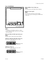
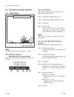
D1611 (A-2) (green) : Power indicator
Lights up when the power is turned on (when passage of
+
5 V line through the IPM-81 board.)
D1601 to D1607, D1609, D1610 (A-5),
D1612 to D1620 (A-5) : Input Status indicator
Indicate the state of the bit stream input.
D1601 to D1607, D1609, D1610 (green) :
Lights up when a signal is properly supplied to the bit
stream input connector.
D1612 to D1620 (orange) :
Lights up when the input signal is not properly.
The correspondance of the indicators and the channels are
as follows:
Channel
Indicator
CH-1 (CH-10)
D1601, D1612
CH-2 (CH-11)
D1602, D1613
CH-3 (CH-12)
D1603, D1614
CH-4 (CH-13)
D1604, D1615
CH-5 (CH-14)
D1605, D1616
CH-6 (CH-15)
D1606, D1617
CH-7 (CH-16)
D1607, D1618
CH-8 (CH-17)
D1609, D1619
CH-9 (CH-18)
D1610, D1620
n
When the BDKP-M1001 is installed (when the input
channel is expanded to 18 channels), expanded channels
are shown in ( ) marks.
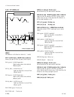
2-2-2. OPM-25 Board
n
The addresses on the board are shown by ( ) marks.
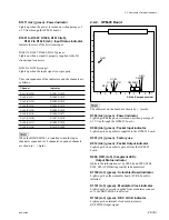
D300 (A-2) (green) : Power indicator
Lights up when the power is turned on (when passage of
+
5 V line through the OPM-25 board.)
D500 (A-6) (green) : Packet Input indicator
Lights up when a packet is supplied to the OPM-25 board.
D501 (C-1) (green) : Factory use
D912 (A-6) (green) : Packet Output indicator
Lights up when a packet is put out from the OPM-25
board.
D900, D913 (A-5) (7-segment LED) :
Output Status indicator
Indicate the information set by S900-4 and S905, S904,
S902, S901 (PID Setting switch) in hexadecimal.
D1100 (A-3) (green) : Scrambler Board indicator
Lights up when the scrambler board (SCR-2 board) is
installed.
D1101 (A-3) (green) : Modulator Clock indicator
Lights up when a clock supplied from modulator connect-
ed to the BDX-M1000 is detected.
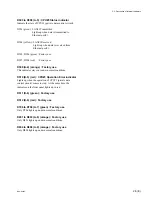
D1102 (A-3) (green) : REF. LOCK indicator
Lights up when internal clock synchronizes to
REF.VIDEO input signal.
7
6
5
4
3
2
1
A
B
C
D
E
F
D300
D501
D1102
D1100
D1101
D900D913
D500
D912
A Side (Component side)

