1-9 (E)
BDX-M1000
1-8-2. OPM-25 Board
n
.
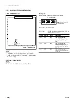
The addresses on the board are shown by ( ) marks.
.
For the switches described “Factory use” or “Unas-
signed”, do not change the factory settings.
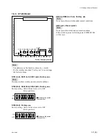
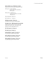
S400 (D-2): Factory use
Factory setting: S400-1 to -3 : ON
S400-4
: OFF
S401 (D-1): Factory use
Factory setting: All switch levers are set to ON.
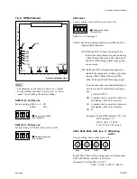
S900 (A-4):
Factory setting: All switch levers are set to ON.
S900-1 to -3: Unassigned
S900-4: Sets the description indicated on D900 and D913
(Output Status indicator).
ON: D900 and D913 (Output Status indicator)
indicate the output number of packets having
a PID (=Packet ID) set by S905, S904, S902
and S901 (PID Setting switch) in the period
of one second.
OFF: D900 and D913 (Output Status indicator)
indicate the output interval (time) of packets
having a PID (=Packet ID) set by S905,
S904, S902 and S901 (PID Setting switch).
It can be converted a hexadecimal display to
time in second (T) by the following expres-
sion:
T=HD
+
(LD/TD)
HD : A number that is converted a hexadeci-
mal display on D900 to a decimal.
LD : A number that is converted a hexadeci-
mal display on D913 to a decimal.
TD : 20
(Example) When D900 indicates “02”, and
D913 indicates “11”:
HD=2, LD=17, TD=20
T=2
+
(17/20)=2.85 second
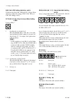
S905, S904, S902, S901 (A-6, 7): PID Setting
switch
Factory setting: All switches are set to 0.
Set the PID (=Packet ID) of output packet in hexadecimal.
S905 is MSB side, and S901 is LSB side.
(Example) To set the PID at “1A7C”:
S905=1, S904=A, S902=7, S901=C
1-8. Settings of Internal Switches
7
6
5
4
3
2
1
A
B
C
D
E
F
S400
S401
S1103
S1101 S900
S903
S905-S901
S504
S503
S502
S501
S500
S1100
S1102
A side (Component side)
1
2
3
4
ON
( indicates the switch
lever position.)
1
2
3
4
ON
( indicates the switch
lever position.)
1
2
3
4
ON
( indicates the switch
lever position.)
8
4
C
0
S905
8
4
C
0
S904
8
4
C
0
S902
8
4
C
0
S901


