14
6. Q-Box & PD-Board Removal
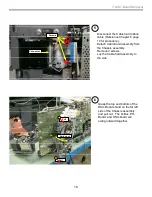
Access & Removal of Q-Box & PD-Board (cont.)
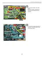
(Digital Module Block DMB )
3
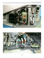
The Q-Box assembly and the
PD-Board (HDMI) can now be
access and removed.
To remove the PD-Board
remove 2 screws, squeeze the
2 white tabs, and disconnect the
2 wires.
Q-Box
Assembly
PD-Board
Screws
Tabs
LVDS
Squeeze
side-tabs
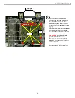
4
To remove the Q-Box module first
disconnect the CableCard ribbon
cable.
Remove 2 white cable clamps that
hold down the ribbon cable.
Disconnect the cable from the
CableCard board by lifting the Tan
connector tab.
CAUTION:
Make sure that the blue
heat-sink pads remain in place.
Also insure that black plastic wire
protector remains in place.
Disconnect the LVDS cable located
at the bottom of the Q -Box assembly
under the gray tape .
Disconnect the i-Link cable.
Heat-sink
Pads
Disconnect
Gently flip
up Tan Tab
Lift clamps
Disconnect
LVDS
Wire Protector
(under wires)
Disconnected
i-Link
Summary of Contents for 2005 SXRD KDS-R50XBR1
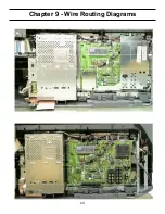
Page 26: ...24 Chapter 9 Wire Routing Diagrams Wire Routing Diagrams ...
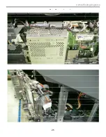
Page 27: ...25 9 Wire Routing Diagrams Wire Routing Diagrams cont ...
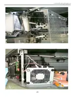
Page 28: ...26 9 Wire Routing Diagrams Wire Routing Diagrams cont ...
Page 29: ...27 9 Wire Routing Diagrams Wire Routing Diagrams cont ...
Page 30: ...28 9 Wire Routing Diagrams Wire Routing Diagrams cont ...


