Manufacturers of Audio Products for AV,
Installed Sound, Broadcast Radio & Broadcast TV
AVN-Commentator Unit
AVN-CU2-DANTE and AVN-CU4-DANTE
Portable commentator units with Dante
®
AoIP interfacing.
H
A
N
D
B
O
K
Page 1: ...Manufacturers of Audio Products for AV Installed Sound Broadcast Radio Broadcast TV AVN Commentator Unit AVN CU2 DANTE and AVN CU4 DANTE Portable commentator units with Dante AoIP interfacing HANDBOOK...
Page 2: ...ion of Sonifex Ltd Unless otherwise noted all names of companies products and persons contained herein are part of a completely fictitious adaptation and are designed solely to document the use of Son...
Page 3: ...8 Friendly Name 38 Password 38 Retype Password 38 Removing Password Protection 38 HTTP Port 38 Address Mode 39 Static IP Address 39 Static Subnet Mask 39 Static Gateway 39 Note 39 Network Defaults AVN...
Page 4: ...evice Config tab 21 Fig 4 3 Renamed device in routing grid 22 Fig 4 4 Device with default channel labels 22 Fig 4 5 Changing receive channel labels 23 Fig 4 6 Changing transmit channel labels 23 Fig 4...
Page 5: ...ck bus to a Dante output group 53 Fig 6 28 Routing transmit channels in Dante Controller 53 Fig 6 29 Adding an input group 54 Fig 6 30 Adding an output group 55 Fig 6 31 Encoder assignments overview 5...
Page 6: ...ifex co uk f Warranty Register Online for an Extended 2 Year Warranty As standard Sonifex products are supplied with a 1 year back to base warranty If you register the product online you can increase...
Page 7: ...erm is 24 months from the date of despatch the Contract means the quotation these Conditions of Sale and any other document incorporated in a contract between the Company and the Purchaser This is the...
Page 8: ...be accurate at the time of the test to the best of the belief and knowledge of the Company and the Company accepts no liability in respect of its accuracy beyond that set out in Condition a f Subject...
Page 9: ...nect the mains supply before removing the equipment covers The cover is connected to earth by means of the fixing screws It is essential to maintain this earth ground connection to ensure a safe opera...
Page 10: ...ruary 2003 along with the related Directive 2002 95 EC on Restrictions of the use of certain Hazardous Substances in electrical and electronic equipment RoHS The Waste Electrical and Electronic Equipm...
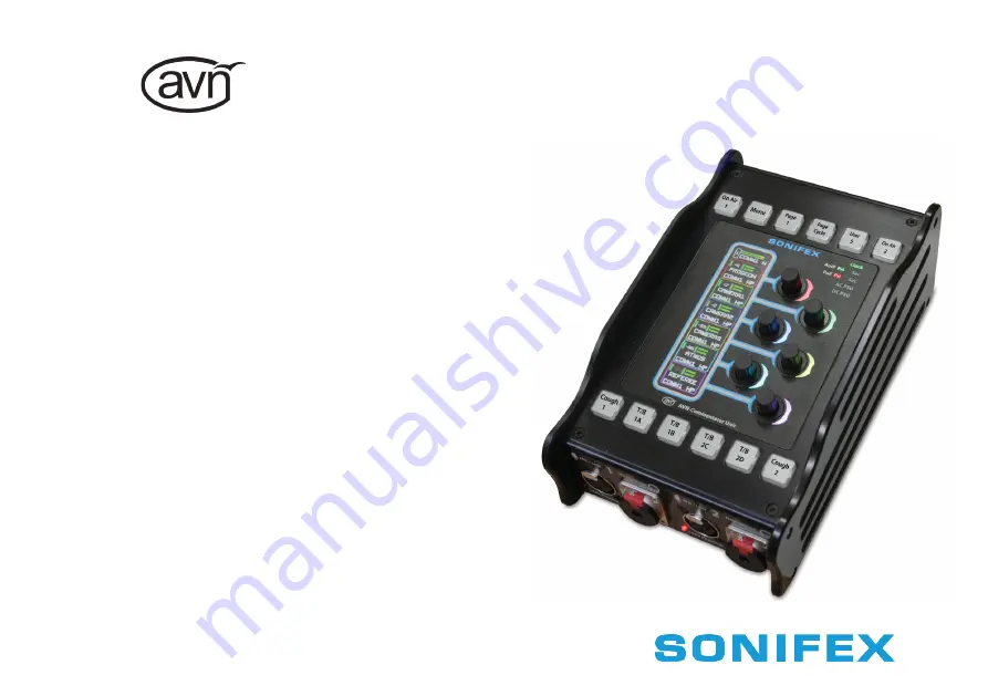
Page 11: ...C mains electricity input on an IEC inlet with universal supply allowing for the varying voltage and frequency requirements of different countries The AVN CU2 provides 6 push button rotary encoders an...
Page 12: ...4 pages labelled 1 4 can be configured on the right hand display For example one page might be used for commentator mics and headphones one might be used for talkback inputs one might be used for phy...
Page 13: ...mentator unit view the Adding Dante Input and Output Groups section for instructions 5 Configuring user buttons on the top panel of the commentator unit view the Front Panel Settings and Control secti...
Page 14: ...r network switch 3 If your network switch supports PoE the unit can be powered using this method and is indicated by the Pri and Sec PoE status LEDs 4 If your switch does not support PoE the DC adapto...
Page 15: ...possible to power the unit with PoE and DC at the same time for redundancy 6 On the AVN CU4 the option to power the unit via an AC supply is also available 7 When AC power is available the AC PSU LED...
Page 16: ...type Command Prompt open Command Prompt and type ipconfig 11 Press enter on the keyboard and note the IP address of your network adaptor connected to the same network switch In this case it is 10 0 2...
Page 17: ...ress settings of the control port select IP Address by pressing the red encoder 15 Modify the IP address so that it is within the same subnet as your PC then select Save using the yellow encoder 16 Th...
Page 18: ...Close using the cyan encoder this closes the menu The unit will then restart to apply the changes 18 Open your web browser type the IP address into the address bar and press enter 19 The device infor...
Page 19: ...an be found under the Configuration tab Click on the Add Output Group icon 2 The Add Output Group window opens Enter a name and then change the type which in this case is a Dante output called Stage o...
Page 20: ...n the routing grid this is symbolised by the green box between the input and output channel Click on the Stage output to configure it 4 Selecting Main Meter will cause any audio on the output to be di...
Page 21: ...t is made to both channels of the AVN DIO6 Stage After a short time two green ticks should be displayed 6 Now any audio on the Main output will be routed to the other Dante device Pressing the On Air...
Page 22: ...me of input or output and function of each encoder 2 Click on the input output or mix point you would like to add an encoder to in this case the Comm1 microphone is selected In the configuration windo...
Page 23: ...tor input 4 The encoder can now also be seen on the top panel of the device the metering for the audio received by the input is show along with the current level adjustment Turn the encoder clockwise...
Page 24: ...18 3 Quick Start Configuring Talkback 1 An input group is added to the device this will be an AoIP stream from the person we want to hear 2 This input is routed directly to the commentators headphones...
Page 25: ...channel from a transmitter is routed to a receiving channel of the Commentator Unit Any audio from the transmitter will now be heard in the commentator s headphones 4 A Dante output group is added to...
Page 26: ...the receiving device 7 Pressing a talkback button will connect the commentators microphone to the talkback bus allowing the commentator to be heard by the receiving device By default if the commentato...
Page 27: ...ante Controller Dante Controller can be downloaded from the official Audinate website you will have to create an Audinate account if you do not already have one https www audinate com products softwar...
Page 28: ...is renamed in this case it is renamed to AVN CU4 Matt Fig 4 3 Renamed device in routing grid Channel Labels The labels of transmit and receive channels can also be changed By default the channels are...
Page 29: ...and select the Receive tab Click a Channel field and enter a new name To edit receive channel labels open the Device View and select the Transmit tab Click a Channel field and enter a new name Fig 4 5...
Page 30: ...are then reflected in the routing grid Filtering Devices Filters are available which allow the user to sort through devices and find the device they need quickly Click the Hide Show Filter Pane icon t...
Page 31: ...and receive channel Initially an hour glass icon is shown on the square to indicate a routing is pending after a short time this then changes to a green circle with a tick to show the routing has been...
Page 32: ...w Enabled Also note the Current Prefix used is set to 69 by default To route audio from an AES67 device to a Dante device with AES67 mode enabled first ensure that the multicast address of the source...
Page 33: ...the example the channel Stage is added to the AES67 multicast flow the Create button is then clicked In Device View the Transmit tab will show the new multicast flow in the Multicast Transmit Flows si...
Page 34: ...owever this can be overriden by selecting the Preferred Leader checkbox Fig 4 16 Clock status tab On devices with the AES67 Mode enabled the Primary v2 Multicast column indicates whether the device is...
Page 35: ...figured such settings include the brightness of LEDs the network configuration and also allows the user to select custom loaded pre sets The rotary encoders are used to control the level pan and mutin...
Page 36: ...ay six encoders with colour indicators and twelve illuminated buttons Fig 5 1 AVN CU2 top panel AVN CU4 DANTE The AVN CU4 DANTE has status LEDs on the right hand side of the panel two TFT displays twe...
Page 37: ...C power supply input Red The DC power supply input is at an unsafe level or no DC power supply is connected Off LED disabled via the embedded web server TFT Display B A TFT display is located to the l...
Page 38: ...socket The AVN CU2 DANTE has two commentator positions and the AVN CU4 DANTE has four commentator positions Each commentator position is configurable via the devices embedded web server Mic Line Input...
Page 39: ...er types for the AoIP connection two RJ45 audio connections a GPIO connector a DC power connector and a reset button The AVN CU4 DANTE has two Ethernet ports for AoIP and PoE two SFP ports for alterna...
Page 40: ...ight of the port flashes if data is being transmitted received on the port the rate of the flashing varies depending on the rate of data transmission Both Ethernet ports are locking in order to preven...
Page 41: ...ly Open Contact Pin 7 Relay Normally Closed Contact Pin 8 Relay Common Pin 9 GPIO Port 6 Pin 10 GPIO Port 7 Pin 11 GPIO Port 8 Pin 12 GPIO Port 9 Pin 13 GPIO Port 10 Pin 14 Fused 50 mA 12V DC Supply P...
Page 42: ...an automatically generated IP address will be used The active IP address for the network port can be found using a service discovery tool such as the Discovery Application which can be found on the S...
Page 43: ...on of the embedded web server which can be accessed on both the Primary and Secondary Ethernet connections The Primary Dante Port Information and the Secondary Dante Port Information shows the configu...
Page 44: ...In this field a password must be retyped this is to make sure you didn t accidentally enter your intended password incorrectly Removing Password Protection Password protection can be removed from a de...
Page 45: ...ure that this IP address is not currently in use on the network This value is not used when the address mode is dynamic Static Subnet Mask This is the subnet mask that will be used for the port when s...
Page 46: ...ort Address Mode Dynamic Static IP Address 192 168 1 101 Static Subnet Mask 255 255 255 0 Static Gateway 0 0 0 0 Network Defaults AVN CU4 Friendly Name AVN CU4 xxxxxxx Where xxxxxxx is the product ser...
Page 47: ...d Control Front Panel The front panel page allows the user to configure the display status LEDs and button assignments The page is updated in real time and shows a live representation of the physical...
Page 48: ...elected the LED is not illuminated DC PSU Status LED Selecting this checkbox enables the DC PSU status LED this LED is illuminated green when power is available on the DC connection If the checkbox is...
Page 49: ...nes Inputs Mix and Outputs For more information on the Encoder Assignments Overview look at the Encoder Assignments section within the Audio Routing section of this manual Fig 6 11 Page name Fig 6 12...
Page 50: ...ed by selecting the Lock Button Row checkbox When locked pressing any button in the row will have no effect A warning message will be displayed on the devices display Fig 6 16 Lock button row Fig 6 17...
Page 51: ...talkback A B C D bus The commentator input to mix is selected using the Comm Pos drop down menu One T B button may be assigned for each commentator per talkback channel The button is shown graphically...
Page 52: ...maximum of twenty four GPIO buttons on the AVN CU4 DANTE When selected the following options are also displayed On LED Colour Off LED Colour Lock Cough The button temporarily takes a selected comment...
Page 53: ...to deactivate the function Comm Pos The Comm Pos drop down menu allows the user to select which commentator microphone the selected function applies to On the AVN CU2 DANTE this option ranges from 1 2...
Page 54: ...be controlled from here Level The audio level is displayed using two metering bars on stereo sources and a single metering bar for mono sources yellow metering is displayed once the audio level rises...
Page 55: ...ge can be used to Add and configure inputs and outputs such as selecting their type and their line up Creating routings between different inputs and outputs Add encoders to inputs outputs and mix poin...
Page 56: ...This allows the user to group inputs from different sources onto a bus then route them all at the same time to physical or AoIP outputs The virtual buses also provide smart functionality for the comm...
Page 57: ...outing webpage of the commentator unit and allow audio routed to channels belonging to Dante Receivers within the Dante Controller application to be used as inputs In this example a channel from AVN D...
Page 58: ...group to show the channels belonging to it The input group can then be routed to the outputs as required In the example a channel is routed to all the commentators headphones Fig 6 25 Routing Dante i...
Page 59: ...commentator activates T B A the commentator can speak to security Fig 6 27 Routing talkback bus to a Dante output group Within the Routing tab of Dante Controller the transmit channel can be routed to...
Page 60: ...the new input group this name is displayed as the label for the input on the inputs section of the grid Select the input type digital and analogue inputs are located on the rear of the device whereas...
Page 61: ...ed as the label for the group on the outputs section of the grid Select the output type digital and analogue outputs are located on the rear of the device whereas Dante outputs are accessible using Da...
Page 62: ...st the name of the input output is displayed then underneath this the functionality of the encoder is displayed If no encoder is assigned to a particular encoder position page the box is greyed out an...
Page 63: ...pan In the encoder tab select the Display Page and Encoder Position to assign the encoder to Then select the Function and Colour of the encoder Only select Lock if you want to prevent the use of the e...
Page 64: ...l inputs shows if the input is unlocked or locked On air status on commentator inputs shows if the input is on air or off air Talkback bus status on commentator inputs shows if a talkback bus is enabl...
Page 65: ...o outputs Set the dBFS level that the limiter associated with the selected output group will activate at The minimum value is 40 dBFS and the maximum value is 0 dBFS Main Meter Applies to outputs When...
Page 66: ...The cut off frequency can be set to a value from 40 Hz to 10000 Hz Encoder Tabs Fig 6 37 Encoder tab of an output configuration window The encoder tab is used to setup an encoder for the correspondin...
Page 67: ...e on points with pan control in the General tab The encoder can be used to pan the audio rotating clockwise pans the audio right and rotating anti clockwise pans the audio left The Pan Mode option als...
Page 68: ...nel is indicated by a green square To quickly remove routings the user can hold the control key and click Whilst the control key is held hovering over a routing turns it red Squares that cannot be rou...
Page 69: ...Apply A complete row of buttons can also be locked by selecting the corresponding checkbox in the Front Panel web page Fig 6 39 Locking a row of buttons Pressing a locked user button will cause the L...
Page 70: ...r clicking it turns to a closed lock indicating the page of encoders is now locked Fig 6 42 Locking a page of encoders The Encoder Assignment Overview on the Audio Routing page shows the currently loc...
Page 71: ...this LED sign to be turned on whenever they are on air therefore they add the event On Air 1 as an input then they add a physical GPIO as an output selecting Physical Port 1 They then click in the wh...
Page 72: ...an output to be triggered for example an input event could be set when DC power is lost When selected the following fields are also displayed Available Events User Button Allows a user button on the...
Page 73: ...available via the primary network port on the device Secondary Link Down Active when no connection is available via the secondary network port on the device AC Power Off AVN CU4 Only Active when the...
Page 74: ...re also displayed Available Buttons Relay Allows the relay available on the GPIO connector to be toggled on and off When selected the following options are also displayed Available Relays Available Po...
Page 75: ...a green lightbulb the connection becomes active this in turn makes the output active indicated by a green lightbulb Remove Connection Hold the control key and click a connection to delete it Alternati...
Page 76: ...SNMP using the OID 1 3 6 1 2 1 1 4 sysContact Community The SNMP community string is used as a form of security if the string is set to public without quotation marks any SNMP master on the network m...
Page 77: ...extract the SWU file from the archive this can be done in Windows by right clicking the archive and selecting extract all Clicking update will then bring up a window explaining the firmware update pro...
Page 78: ...he unit will automatically reboot to load the new configuration settings This takes approximately 25 seconds during which time a progress page will be shown If the settings of the network port the bro...
Page 79: ...allows the commentator time to acknowledge that they have pressed an encoder When the system menu opens the following items are displayed Network Brightness Status Config Audio Close You can exit this...
Page 80: ...n the brightness sub menu all the encoder LED bars are on this allows the level of each of the colours to be seen Pressing the first encoder causes the percentage to be highlighted the brightness can...
Page 81: ...e gain sub menu the pre amp gain measured in dB can be adjusted from 16 dB to 76 dB Phantom In the phantom sub menu phantom power can be enabled or disabled Line up The line up level can be adjusted b...
Page 82: ...n After changing any network settings via Ember the unit has to be rebooted to apply the changes The network node contains the options friendly_name The name given to the device by the user click Chan...
Page 83: ...entator input you would like to activate talkback for In the General tab select A B C or D from Active Talkbacks Level Control Navigate to the Audio Routing web page Click on the input mix point or ou...
Page 84: ...ne Mode 10k electronically balanced Preamp Gain Mic Mode User selectable 16dB to 76dB in 3dB steps Ref 18dBu 0dBFS 0dBFS Line up Mic Mode 58dBu Max preamp gain 2dBu Min preamp gain 0dBFS Line up Line...
Page 85: ...u 1kHz THD N Analogue Mode 107dBFS 30dBFS 20Hz 20kHz 20kHz BW Noise Analogue Mode 107dBFS 20kHz BW Headphone Outputs Drive Capability Drives 150mW into 32 to 600 headphones 0dBFS Line up Fixed 0dBFS 1...
Page 86: ...Typical PSE Power Usage 13 W Max PSE Power Usage 15 4 W Equipment Type AVN CU2 DANTE Dante Commentator Unit 2 Commentators Physical Specification Dimensions Raw 13 5cm W x 23cm D x 9 0cm H rear 6 6cm...
Page 87: ...balanced Preamp Gain Mic Mode User selectable 16dB to 76dB in 3dB steps Ref 18dBu 0dBFS 0dBFS Line up Mic Mode 58dBu Max preamp gain 2dBu Min preamp gain 0dBFS Line up Line Mode User selectable 15dBu...
Page 88: ...BW Headphone Outputs Drive Capability Drives 150mW into 32 to 600 Headphones 0dBFS Line up Fixed 0dBFS 18dBu Frequency Response 0 0 2dB 20Hz to 22kHz Ref 0dBu 1kHz THD N 108dBFS 30dBFS 20Hz 20kHz 20kH...
Page 89: ...W max Fuse Rating Anti surge fuse 2A 20 x 5mm PoE Power Standard 802 3at Type 2 Class 4 PD Power Range 12 95 W to 25 50 W Typical PSE Power Usage 20W Max PSE Power Usage 30W Equipment Type AVN CU4 DAN...
Page 90: ...www sonifex co uk t 44 0 1933 650 700 f 44 0 1933 650 726 sales sonifex co uk...