background image

FR

Manuel d’installation

NL


Installatiehandleiding

EN


Installation instructions

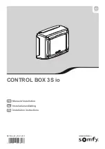
CONTROL BOX 3S io

D811864_02_20-01-2015

8   027908

4 0 3 8 0 3

Summary of Contents for Control Box 3S io

Page 1: ...FR Manuel d installation NL Installatiehandleiding EN Installation instructions CONTROL BOX 3S io D811864_02_20 01 2015 8 027908 4 0 3 8 0 3 ...

Page 2: ...liste des paramètres 12 Signification des différents paramètres 12 Affichage des valeurs de paramètre 12 Mémorisation des télécommandes 15 Informations générales 15 Mémorisation des télécommandes Keygo io 15 Mémorisation des télécommandes Keytis io 16 Mémorisation des télécommandes 3 touches Telis io Telis Composio io etc 18 effacement des télécommandes et de tous les réglages 19 Effacement indivi...

Page 3: ...onnel de la motorisation et de l automatisation de l habitat Introduction Informations importantes Ce produit est une armoire de commande pour des portails battants en usage résidentiel Pour être conforme à la norme EN 60335 2 103 ce produit doit être impérativement installé avec un moteur Somfy L ensemble est désigné sous le nom de motorisation Ces instructions ont notamment pour objectif de sati...

Page 4: ...adhésifs pour fixer la motorisation ATTENTION Installer tout dispositif de commande fixe à une hauteur d au moins 1 5 m et en vue du portail mais éloigné des parties mobiles Après installation s assurer que le mécanisme est correctement réglé le dispositif de débrayage manuel fonctionne correctement la motorisation change de sens quand le portail rencontre un objet de 50 mm de haut positionné à mi...

Page 5: ...pprentissage Validation de la sélection d un paramètre Validation de la valeur d un paramètre Appui 2 s mémorisation des télécommandes Appui 7 s effacement de toutes les télécommandes Modification de la valeur d un paramètre appui bref défilement paramètre par paramètre appui maintenu défilement rapide des paramètres Utilisation du mode marche forcée Composition du kit Rep Désignation 1 Interface ...

Page 6: ...e fermer en dernier sur le connecteur M1 bornes 11 et 12 2 Câbler le second moteur sur le connecteur M2 bornes 14 et 15 Nota pour les moteurs Ixengo câbler le fin de course de M1 câble blanc sur la borne 13 et le fin de course de M2 câble blanc sur la borne 16 Une étape de vérification du câblage des moteurs et du sens d ouverture des vantaux est prévue au début de la mise en service de la motoris...

Page 7: ...L exécution de cette procédure par un canal déjà mémorisé provoque l effacement de celui ci 1 Appuyer sur la touche PROG 2 s de l interface de programmation L écran affiche F0 2 Appuyer simultanément sur les touches extérieure droite et extérieure gauche de la télécommande Le voyant de la télécommande clignote 3 Appuyer sur la touche de la télécommande qui commandera l ouverture totale du portail ...

Page 8: ...ique protection thermique etc l appui sur une touche de commande interface armoire télécommande mémorisée point de commande câblé etc En cas d interruption l afficheur indique H0 l armoire revient en mode Attente de réglage En mode Attente de réglage les commandes radio fonctionnent et le mouvement du portail s effectue à vitesse très réduite Ce mode ne doit être utilisé que pendant l installation...

Page 9: ...nement dégradé En 24 V fonctionnement normal 11 12 13 Fin de course Moteur 1 Ixengo uniquement 14 15 16 Fin de course Moteur 2 Ixengo uniquement 17 18 24 V 15 W 0 V Sortie feu orange 24 V 15 W 19 20 24 V 0 V Alimentation 24 V accessoires 1 2 A max pour l ensemble des accessoires sur toutes les sorties 21 22 23 24 24 V 0 V Commun Contact Alimentation sécurités Entrée sécurité 1 Cellules Permanent s...

Page 10: ...que du fonctionnement de la cellule photoélectrique à chaque mouvement du portail Si le test de fonctionnement se révèle négatif aucun mouvement du portail n est possible jusqu au passage en mode de fonctionnement homme mort au bout de 3 minutes L installation de cellules photoélectriques AVEC AUTO TEST P07 2 est obligatoire dans le cas de l utilisation d un boîtier Tahoma pour la commande de l au...

Page 11: ...2 2 sec Cell 2 5 TX RX TX RX TX1 RX1 TX2 RX2 1 2 21 22 22 TX1 RX1 1 2 3 23 21 5 3 RX2 1 2 21 22 22 TX2 RX2 1 2 3 5 RX1 21 5 24 24V dc 1 9 2 0 2 3 2 4 2 1 24V Cell 2 2 sec Cell 2 5 24V dc 1 9 2 0 2 3 2 4 2 1 24V Cell 2 2 sec Cell ash 18 24V dc 1 9 2 0 2 3 2 4 2 1 24V Cell 2 2 sec Cell 2 5 TX1 RX1 TX2 RX2 1 2 23 24 24 TX1 RX1 1 2 3 23 5 1 2 23 24 24 TX2 RX2 1 2 3 23 5 24V dc 1 9 2 0 2 3 2 4 2 1 24V ...

Page 12: ...1 V V 19 20 31 32 19 20 24V dc 1 9 2 0 2 3 2 4 2 1 24V Cell 2 2 sec Cell 3 0 3 1 3 2 Lock 2 5 2 6 2 7 2 8 2 9 Sec Prog Test Sec 24V dc 1 9 2 0 2 3 2 4 2 1 24V Cell 2 2 sec Cell 3 0 3 1 3 2 Lock 2 5 2 6 2 7 2 8 2 9 Sec Prog Test Sec 2 4 3 5 Ant 33 34 3 2 1 1 9 1 0 Batt 4 7 A 5 6 Lamp 500 W max 8 9 2 24V dc 1 9 2 0 2 3 2 4 2 1 24V Cell 2 2 sec Cell 3 0 Lock 2 5 2 6 2 7 2 8 2 9 Sec Prog Test Sec K M ...

Page 13: ...grammée au paramètre P02 un appui sur la touche de la télécommande pendant l ouverture est sans effet un appui sur la touche de la télécommande pendant la fermeture provoque la réouverture un appui sur la touche de la télécommande pendant la temporisation de fermeture relance la temporisation le portail se fermera à l issue de la nouvelle temporisation Si un obstacle est présent dans la zone de dé...

Page 14: ...nterdit si une barre palpeuse est connectée sur l entrée de sécurité programmable 1 recommandé pour une application barre palpeuse 2 recommandé pour une application cellule P12 Préavis du feu orange 0 sans préavis 1 avec préavis de 2 s avant mouvement Si le portail donne sur la voie publique sélectionner obligatoirement avec préavis P12 1 P13 Sortie éclairage de zone 0 inactive 1 fonctionnement pi...

Page 15: ...rentissage En cas de modification de ce paramètre l installateur doit impérativement vérifier que la limitation des forces est conforme à l annexe A de la norme EN12 453 ou installer une barre palpeuse Si le couple est trop faible il existe un risque de détections d obstacle intempestives Si le couple est trop élevé il existe un risque de non conformité de l installation à la norme P26 Limitation ...

Page 16: ...opie d une télécommande déjà mémorisée La mémorisation s effectue individuellement pour chaque touche de commande La mémorisation d une touche déjà mémorisée provoque l effacement de celle ci Signification des codes affichés Code Désignation Add Mémorisation réussie d une télécommande monodirectionnelle Mémorisation réussie d une télécommande bidirectionnelle dEL Effacement d une touche déjà mémor...

Page 17: ...uits io homecontrol avec au moins une télécommande bidirectionnelle mémorisée Si la télécommande Keytis io à mémoriser est la première télécommande du système alors passer directement à l étape Mémorisation de la télécommande Keytis io 1 Placer la télécommande mémorisée dans le mode de transfert de clé Télécommandes Keytis io Telis io Impresario io Composio io appuyer sur le bouton KEY jusqu à all...

Page 18: ... C1 Add 2s C1 C1 F0 Add F1 Mémorisation par recopie d une télécommande Keytis io déjà mémorisée Recopie complète d une télécommande Keytis io Cette opération permet de recopier à l identique l ensemble des touches d une télécommande déjà mémorisée La nouvelle télécommande ne doit pas être déjà mémorisée sur un autre automatisme S assurer que la nouvelle télécommande a mémorisé la clé système 1 App...

Page 19: ...émoriser Télécommande mémorisée Recopie individuelle d une touche de télécommande Keytis io Cette opération permet de recopier la mémorisation d une seule touche d une télécommande déjà mémorisée sur une touche vide d une nouvelle télécommande S assurer que la nouvelle télécommande a mémorisé la clé système 1 Appuyer sur le bouton PROG de la télécommande déjà mémorisée jusqu à l allumage du voyant...

Page 20: ... F0 rSt C1 Ré initialisation générale d une télécommande Keytis io Appuyer simultanément sur les boutons PROG et KEY Ceci provoque l effacement général de la programmation toutes les touches l effacement de tous les paramétrages de la télécommande voir notice de la télécommande Keytis io la modification de la clé système mémorisée par la télécommande Effacement de tous les réglages Provoque l effa...

Page 21: ...Commentaires H0 Attente de réglage L appui sur la touche SET pendant 2 s lance le mode auto apprentissage Hc1 Attente de réglage Alimentation 9 6 V Affichage lors du fonctionnement sur batterie de secours 9 6 V Hu1 Attente de réglage Alimentation 24 V Affichage lors du fonctionnement sur batterie de secours 24 V H1 Attente lancement auto apprentissage L appui sur la touche OK permet de lancer le c...

Page 22: ...limentation accessoires est coupée suite à une surcharge consommation excessive Rappel consommation maximum accessoires 1 2 A Vérifier la consommation des accessoires raccordés E14 Détection intrusion Fonction réinjection de courant Fonctionnement normal tentative d intrusion réinjection de courant mise en oeuvre E15 Défaut première mise sous tension de l armoire alimentée par batterie de secours ...

Page 23: ... antenne io Réf 9013953 Entrée batterie de secours Autonomie Oui compatible pack batterie Réf 9001001 24 heures 3 cycles Temps de charge 48 h FONCTIONNEMENT Mode marche forcée Par appui sur bouton de commande moteur Pilotage indépendant de l éclairage déporté Oui Temporisation d éclairage après mouvement Programmable 0 à 600 s Mode fermeture automatique Oui temporisation de refermeture programmabl...

Page 24: ...erschillende parameters 12 Weergave van de waarden van de parameters 12 Programmeren van de afstandsbedieningen 15 Algemene informatie 15 Programmeren van de Keygo io afstandsbedieningen 15 Programmeren van de Keytis io afstandsbedieningen 16 Programmeren van de afstandsbedieningen met 3 toetsen Telis io Telis Composio io enz 18 wissen van de afstandsbedieningen en van alle afstellingen 19 Afzonde...

Page 25: ...erd moeten worden door een erkende installateur van automatiseringssystemen in woningen Inleiding Belangrijke informatie Dit product is een bedieningskast voor klaphekken voor gebruik in de woonomgeving Om te voldoen aan de norm EN 60335 2 103 moet het product verplicht geïnstalleerd worden met een Somfy motor Het geheel wordt aangeduid als de motorisatie Deze instructies zijn geschreven binnen he...

Page 26: ...n kleefmiddelen om de motorisatie te bevestigen LET OP Installeer vaste bedieningsorganen op een hoogte van ten minste 1 5 m en in het zicht van het hek maar buiten het bereik van de bewegende delen Controleer na de installatie dat het mechanisme correct is ingesteld de handmatige ontkoppeling correct werkt de motorisatie verandert van richting als het hek een voorwerp van 50 mm hoogte tegenkomt d...

Page 27: ...n de selectie van een parameter Bevestiging van de waarde van een parameter Druk van 2 s programmeren van de afstandsbedieningen Druk van 7 s wissen van alle afstandsbedieningen Wijziging van de waarde van een parameter korte druk doorlopen parameter voor parameter ingedrukt houden snel doorlopen van de parameters Gebruik van de geforceerde werking Samenstelling van de set Nr Omschrijving 1 Progra...

Page 28: ...et sluiten aan op de stekker M1 klemmen 11 en 12 2 Sluit de tweede motor aan op de stekker M2 klemmen 14 en 15 N B sluit voor de Ixengo motoren het eindpunt van M1 witte kabel aan op klem 13 en het eindpunt van M2 witte kabel op klem 16 Een controle van de aansluiting van de motoren en van de richting van het openen van de vleugels is voorzien bij het begin van het in bedrijf stellen van de motori...

Page 29: ...de draden van M2 op de klemmen 14 en 15 2s H0 Add H0 F0 Bij de uitvoering van deze procedure door een kanaal dat al geprogrammeerd is wordt het kanaal gewist 1 Druk op de toets PROG 2 s van de programmeringsinterface Het scherm geeft F0 weer 2 Druk tegelijk op de toetsen rechtsbuiten en linksbuiten van de afstandsbediening De led van de afstandsbediening knippert 3 Druk op de toets van de afstands...

Page 30: ...op een bedieningstoets interface kast geprogrammeerde afstandsbediening bedraad bedieningspunt enz In geval van onderbreking geeft het display H0 aan de kast gaat terug naar de modus In afwachting van afstelling In de modus In afwachting van afstelling werken de radiocommando s en het bewegen van het wordt met erg lage snelheid uitgevoerd Deze modus mag alleen gebruikt worden tijdens de installati...

Page 31: ...werking Bij 24 V normale werking 11 12 13 Eindpunt Motor 1 Alleen Ixengo 14 15 16 Eindpunt Motor 2 Alleen Ixengo 17 18 24 V 15 W 0 V Uitgang oranje licht 24 V 15 W 19 20 24 V 0 V Voeding 24 V accessoires Max 1 2 A voor alle accessoires op alle uitgangen 21 22 23 24 24 V 0 V Gemeenschappelijk Contact Voeding veiligheden Ingang veiligheid 1 Cellen Permanent indien zelftest niet geselecteerd is bestu...

Page 32: ...matische test van de werking van de foto elektrische cel uitgevoerd worden bij elke beweging van het hek Als de werkingstest negatief blijkt is er geen enkele beweging van het hek mogelijk tot het overgaan naar de dodemans werkingsmodus na 3 minuten De installatie van foto elektrische cellen MET ZELFTEST P07 2 is verplicht als een Tahoma eenheid gebruikt wordt voor de bediening van het automatisch...

Page 33: ...2 2 sec Cell 2 5 TX RX TX RX TX1 RX1 TX2 RX2 1 2 21 22 22 TX1 RX1 1 2 3 23 21 5 3 RX2 1 2 21 22 22 TX2 RX2 1 2 3 5 RX1 21 5 24 24V dc 1 9 2 0 2 3 2 4 2 1 24V Cell 2 2 sec Cell 2 5 24V dc 1 9 2 0 2 3 2 4 2 1 24V Cell 2 2 sec Cell ash 18 24V dc 1 9 2 0 2 3 2 4 2 1 24V Cell 2 2 sec Cell 2 5 TX1 RX1 TX2 RX2 1 2 23 24 24 TX1 RX1 1 2 3 23 5 1 2 23 24 24 TX2 RX2 1 2 3 23 5 24V dc 1 9 2 0 2 3 2 4 2 1 24V ...

Page 34: ...1 V V 19 20 31 32 19 20 24V dc 1 9 2 0 2 3 2 4 2 1 24V Cell 2 2 sec Cell 3 0 3 1 3 2 Lock 2 5 2 6 2 7 2 8 2 9 Sec Prog Test Sec 24V dc 1 9 2 0 2 3 2 4 2 1 24V Cell 2 2 sec Cell 3 0 3 1 3 2 Lock 2 5 2 6 2 7 2 8 2 9 Sec Prog Test Sec 2 4 3 5 Ant 33 34 3 2 1 1 9 1 0 Batt 4 7 A 5 6 Lamp 500 W max 8 9 2 24V dc 1 9 2 0 2 3 2 4 2 1 24V Cell 2 2 sec Cell 3 0 Lock 2 5 2 6 2 7 2 8 2 9 Sec Prog Test Sec K M ...

Page 35: ...toets van de afstandsbediening tijdens het openen heeft geen effect een druk op de toets van de afstandsbediening tijdens het sluiten zorgt voor het weer openen een druk op de toets van de afstandsbediening tijdens de tijdsduur van het sluiten start de tijdsduur opnieuw het hek sluit aan het eind van de nieuwe tijdsduur Als er een obstakel aanwezig is in de detectiezone van de cellen dan sluit het...

Page 36: ...werking 2 automatische bestuurde werking 0 er wordt geen rekening gehouden met de uitgang zoneverlichting 1 de besturing van de zoneverlichting vindt plaats met een afstandsbediening 2 de besturing van de zoneverlichting vindt plaats met een afstandsbediening als het hek gestopt is de zoneverlichting gaat automatisch aan als het hek in beweging is en blijft branden aan het eind van de beweging tij...

Page 37: ...hte obstakeldetecties Indien het koppel te hoog is bestaat er een risico dat de installatie niet conform de norm is P26 Beperking van het openingskoppel M1 P27 Beperking van het vertragingskoppel bij sluiten M1 P28 Beperking van het vertragingskoppel bij openen M1 P29 Beperking van het sluitingskoppel M2 P30 Beperking van het openingskoppel M2 P31 Beperking van het vertragingskoppel bij sluiten M2...

Page 38: ...rogrammeerde afstandsbediening Het programmeren gebeurt voor elke bedieningstoets afzonderlijk Door het programmeren van een reeds geprogrammeerde toets wordt de bestaande programmering gewist Betekenis van de weergegeven codes Code Omschrijving Add Programmeren van een eenrichtings afstandsbediening geslaagd Programmeren van een tweerichtings afstandsbediening geslaagd dEL Wissen van een reeds ge...

Page 39: ...ducten bevat met ten minste één geprogrammeerde tweerichtings afstandsbediening Als de te programmeren Keytis io afstandsbediening de eerste afstandsbediening van het systeem is ga dan direct naar de stap Programmeren van de Keytis io afstandsbediening 1 Breng de geprogrammeerde afstandsbediening in de codeverzendmodus Keytis io Telis io Impresario io Composio io afstandsbedieningen druk op de toe...

Page 40: ...orden alle toetsen van een reeds geprogrammeerde afstandsbediening gekopieerd De nieuwe afstandsbediening mag niet reeds geprogrammeerd zijn in een ander systeem Zorg ervoor dat de systeemcode is geprogrammeerd in de nieuwe afstandsbediening 1 Druk op de toets PROG van de reeds geprogrammeerde afstandsbediening tot de groene led brandt 2 s 2 Druk kort op de toets PROG van de nieuwe afstandsbedieni...

Page 41: ...tandsbediening Geprogrammeerde afstandsbediening Afzonderlijk kopiëren van toets van een Keytis io afstandsbediening Hiermee kan een enkele toets van een reeds geprogrammeerde afstandsbediening gekopieerd worden naar een ongebruikte toets van een nieuwe afstandsbediening Zorg ervoor dat de systeemcode is geprogrammeerd in de nieuwe afstandsbediening 1 Druk op de toets PROG van de reeds geprogramme...

Page 42: ... tegelijk op de toetsen PROG en KEY Dit zorgt voor het totaal wissen van de programmering alle toetsen het wissen van alle instellingen van de afstandsbediening zie de handleiding van de Keytis io afstandsbediening het veranderen van de door de afstandsbediening geprogrammeerde systeemcode Afzonderlijk wissen van een toets van een Keytis io of Keygo io afstandsbediening Wissen van alle afstellinge...

Page 43: ...de zelfprogrammeringsmodus Hc1 In afwachting van de afstelling voeding 9 6 V Weergave tijdens werking op noodaccu 9 6 V Hu1 In afwachting van de afstelling voeding 24 V Weergave tijdens werking op noodaccu 24 V H1 In afwachting van het starten van de zelfprogrammering Met een druk op toets OK start de zelfprogrammeringscyclus Met een druk op de toetsen of is de bediening van de motor in geforceerd...

Page 44: ...em aanhoudt E13 Storing voeding accessoires De voeding van de accessoires is onderbroken ten gevolge van een overbelasting extreem verbruik Opmerking maximum stroomverbruik van de accessoires 1 2 A Controleer het stroomverbruik van de aangesloten accessoires E14 Storing inbraak Stroominvoerfunctie Normale werking inbraakpoging stroominvoer geactiveerd enz E15 Storing bij eerste keer onder spanning...

Page 45: ...fstandigheid Ja compatibel accupakket Ref 9001001 24 uur 3 cycli Oplaadtijd 48 u WERKING Modus geforceerde werking Door de bedieningsknop van de motor in te drukken Onafhankelijke besturing van de buitenverlichting Ja Tijdsduur van de verlichting na beweging Programmeerbaar 0 tot 600 s Modus automatische sluiting Ja sluitvertraging programmeerbaar van 0 tot 255 min Waarschuwing oranje licht Progra...

Page 46: ...dvanced parameter setting 12 Navigating the parameter list 12 Meaning of different parameters 12 Parameter value display 12 Memorising the remote controls 15 General information 15 Memorising the Keygo io remote controls 15 Memorising the Keytis io remote controls 16 Memorising 3 button remote controls Telis io Telis Composio io etc 18 clearing the remote controls and all settings 19 Clearing indi...

Page 47: ...omation installer Introduction Important information This product is a control cabinet for swing gates for residential use To ensure compliance with the standard EN 60335 2 103 this product must be installed with a Somfy motor The assembly is together designated as a motorisation The main purpose of these instructions is to satisfy the requirements of the aforementioned standard and to ensure the ...

Page 48: ...il installation is complete Do not use adhesive to secure the motorisation ATTENTION Install any fixed control device at a height of at least 1 5 m and within sight of the gate but away from moving parts After installation ensure that the mechanism is correctly adjusted the manual back release device is operating correctly the motorisation changes direction when the gate encounters an object 50 mm...

Page 49: ...o programming cycle confirm parameter selection confirm parameter value Press 2 s memorise the remote controls Press 7 s clear all remote controls modify a parameter value short press scroll through individual parameters press and hold scroll rapidly through parameters use of forced operating mode Composition of the kit No Description 1 Programming interface 2 Plug in terminals 3 Cover 4 Cover scr...

Page 50: ...o connector M1 terminals 11 and 12 2 Wire the second motor to connector M2 terminals 14 and 15 Note for Ixengo motors wire the end limit for M1 white cable to terminal 13 and the end limit for M2 white cable to terminal 16 A stage for verifying the motor wiring and the gate leaf ope ning direction is included at the start of the motor commis sioning procedure on page 6 Connecting to the mains powe...

Page 51: ... F0 If this procedure is carried out using a channel which has already been memorised this channel will be cleared 1 Pressandholdthe PROG button 2s ontheprogramminginterface The screen displays F0 2 Press the outer left and right buttons on the remote control together The remote control indicator light flashes 3 Press the button of the remote control that will open the gate fully The screen displa...

Page 52: ...ace memorised remote control wired control point etc In case of interruption the display indicates H0 and the control box returns to Awaiting setting mode In Awaiting setting mode the radio controls operate and the gate moves very slowly This mode must only be used during installation Auto programming must be successfully performed before the gate can be used normally During auto programming if th...

Page 53: ...ge power supply input At 9 V degraded operation At 24 V normal operation 11 12 13 End limit Motor 1 Ixengo only 14 15 16 End limit Motor 2 Ixengo only 17 18 24 V 15 W 0 V 24 V 15 W orange light output 19 20 24 V 0 V 24 V accessories power supply 1 2 A max for all accessories on all outputs 21 22 23 24 24 V 0 V Shared Contact Safety device power supply Safety input 1 Cells Permanent if autotest not...

Page 54: ...st to be carried out to check the operation of the photoelectric cell each time the gate moves If the operating test result is negative the gate cannot be moved until the operating mode changes to deadman operation after 3 minutes It is compulsory to install photoelectric cells WITH AUTOTEST P07 2 if the automatic control device is being controlled by a Tahoma control box Orange light Fig 3 Progra...

Page 55: ...2 2 sec Cell 2 5 TX RX TX RX TX1 RX1 TX2 RX2 1 2 21 22 22 TX1 RX1 1 2 3 23 21 5 3 RX2 1 2 21 22 22 TX2 RX2 1 2 3 5 RX1 21 5 24 24V dc 1 9 2 0 2 3 2 4 2 1 24V Cell 2 2 sec Cell 2 5 24V dc 1 9 2 0 2 3 2 4 2 1 24V Cell 2 2 sec Cell ash 18 24V dc 1 9 2 0 2 3 2 4 2 1 24V Cell 2 2 sec Cell 2 5 TX1 RX1 TX2 RX2 1 2 23 24 24 TX1 RX1 1 2 3 23 5 1 2 23 24 24 TX2 RX2 1 2 3 23 5 24V dc 1 9 2 0 2 3 2 4 2 1 24V ...

Page 56: ...1 V V 19 20 31 32 19 20 24V dc 1 9 2 0 2 3 2 4 2 1 24V Cell 2 2 sec Cell 3 0 3 1 3 2 Lock 2 5 2 6 2 7 2 8 2 9 Sec Prog Test Sec 24V dc 1 9 2 0 2 3 2 4 2 1 24V Cell 2 2 sec Cell 3 0 3 1 3 2 Lock 2 5 2 6 2 7 2 8 2 9 Sec Prog Test Sec 2 4 3 5 Ant 33 34 3 2 1 1 9 1 0 Batt 4 7 A 5 6 Lamp 500 W max 8 9 2 24V dc 1 9 2 0 2 3 2 4 2 1 24V Cell 2 2 sec Cell 3 0 Lock 2 5 2 6 2 7 2 8 2 9 Sec Prog Test Sec K M ...

Page 57: ...trol during opening has no effect pressing a button on the remote control during closing causes it to reopen pressing a button on the remote control during the closing time delay restarts the time delay the gate will close when the new time delay has elapsed If there is an obstacle in the cells detection zone the gate will not close It will close once the obstacle is removed 4 automatic cell block...

Page 58: ...rea lighting output 0 inactive 1 controlled operation 2 automatic controlled operation 0 the area lighting output is not taken into account 1 the area lighting is remotely controlled 2 the area lighting is remotely controlled when the gate is stationary the area lighting comes on automatically when the gate is moving and remains on when it stops moving for the duration of the time delay programmed...

Page 59: ...tic obstacle detection If the torque is too high the installation may not comply with the standard P26 M1 opening torque limitation P27 M1 closing slowdown torque limitation P28 M1 opening slowdown torque limitation P29 M2 closing torque limitation P30 M2 opening torque limitation P31 M2 closing slowdown torque limitation P32 M2 opening slowdown torque limitation P37 Wired control inputs 0 complet...

Page 60: ... a previously memorised remote control Each control button is memorised individually Memorising a button which has already been memorised will clear this button s function Meaning of displayed codes Code Description Add Successful memorisation of a monodirectional remote control Successful memorisation of a bidirectional remote control dEL Delete a previously memorised button rEF Unsuccessful memo...

Page 61: ...eady includes other io homecontrol products with at least one memorised bidirectional remote control If the Keytis io remote control to be memorised is the first remote control on the system go directly to the step Memorising the Keytis io remote control 1 Setting the memorised remote control to key transfer mode Keytis io Telis io Impresario io Composio io remote controls press the KEY button unt...

Page 62: ...opy all the buttons on a previously memorised remote control The new remote control must not be memorised for another automatic control system Ensure that the new remote control has memorised the system key 1 Press the PROG button on the memorised remote control until the green indicator light comes on 2 s 2 Briefly press the PROG button on the new remote control Wait for the second beep and the g...

Page 63: ... control memorised Copying individual buttons on the Keytis io remote control This operation is used to copy the memorisation of a single button on a previously memorised remote control to a blank button on a new remote control Ensure that the new remote control has memorised the system key 1 Press the PROG button on the memorised remote control until the green indicator light comes on 2 s 2 Brief...

Page 64: ...tis io remote control general reset Press the PROG and KEY buttons together This causes the programming to be completely cleared all buttons all the settings on the remote control to be cleared refer to the instructions for the Keytis io remote control the system key memorised by the remote control to be modified Clearing individual buttons on the Keytis io or Keygo io remote controls Clearing all...

Page 65: ... awaiting auxiliary output control memorisation F3 F3 Awaiting remote control memorisation for auxiliary output control Pressing a button on the remote control allocates this button to the auxiliary output control Pressing PROG once more switches to awaiting remote control memorisation for operation in complete opening mode F0 diagnostics Operating code display Code Description Comments C1 Awaitin...

Page 66: ...wer supply fault The accessories power supply cuts out following an overload excessive consumption N B maximum accessories consumption 1 2 A Check the consumption of the connected accessories E14 Intrusion detection Current reinjection function Normal operation attempted intrusion current reinjection activated etc E15 Fault when the control box supplied by the backup battery is first switched on D...

Page 67: ...fset aerial input Yes compatible with io aerial Ref 9013953 Backup battery input Life Yes compatible with battery pack Ref 9001001 24 hours 3 cycles Charge time 48 hours OPERATION Forced operating mode By pressing the motor control button Independent remote lighting control Yes Timed lighting after movement Programmable 0 to 600 s Automatic closing mode Yes programmable reclosing time delay from 0...

Page 68: ...Somfy SAS capital 20 000 000 Euros RCS Annecy 303 970 230 01 2015 Somfy 50 avenue du Nouveau Monde BP 152 74307 Cluses Cedex France www somfy com 5105536B ...

Reviews: