background image

C

L

L

L

N

N

N

Zone 1

Zone 2

PE

Error

+

C

E

x

te

rn

a

l

C

o

m

m

a

n

d

Z

o

n

e

 2

1

+

1

Out
Side

2

2

+

+

C

C

C

E

x

te

rn

a

l

C

o

m

m

a

n

d

Z

o

n

e

 1

RK

IB

C

C

PE

PE

1

1

Outside

2

2

Zone 2

Zone 1

C

C

C

C

L

L

L

N

N

N

IB

230V

IB

C

230V

Motor

Motor

Zone 1

Zone 2

C

C

C

L

L

L

N

N

N

RK

Motor

L

N

RK

Motor

L

N

Zone 1

Zone 2

C

C

C

L

L

L

N

N

N

Zone 1

Zone 2

Motor

230V

Motor

230V

C

C

C

L

L

L

N

N

N

Zone 1

Zone 2

RK

L

N

Motor

230V

Motor

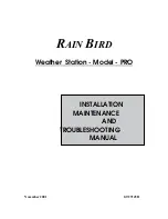
Please study the appropriate motor relay’s installation guide.

The number of motors that can be connected in RK mode is dependent on the main fuse 
used. Normally you can count one motor per 1A. This means a 10A fuse allows maximum 10 
motors to be connected.

IB

RK

Motor direct

Motor direct 

+ RK

6

h. Motor connEction principlES

Animeo Solo consists of two different modes to control motor relays, IB and RK. Select the type 
you are using. IB network mode is default. 

(The switch is located on the printed circuit board.)

IB network mode

IB is Somfy’s standard communication mode. Typical motor relays with 
IB mode are Somfy CD4, Somfy animeo Motor controllers and Somfy 
Centralis IB. 

RK network mode

RK is an older network mode using no electronics or “intelligence” in 
the motor relays. A typical motor relay with RK is Somfy RK2. RK mode 
is also used when connecting one AC motor directly to the controller.

 Important!

It’s very important that you select the correct network mode for your installation. Otherwise 
there is risk that you will damage the products. If more than one motor is to be connected 
to a zone, a motor relay must be used.

i. SElEct nEtWork MoDE

UK

Summary of Contents for 1860143

Page 1: ...L Telep t si tmutat E DK ES FR HU IT NL NO PT RO FI CZ DE PL Guida all installazione K ES FR HU IT NL NO PT RO FI CZ DE PL Installatiehandleiding UK SE DK ES FR HU IT NL NO PT RO FI CZ DE PL Installas...

Page 2: ...wij u om deze aanwijzingen te lezen en op te volgen Een onjuiste installatie kan ernstig persoonlijk letsel veroorzaken Dit product moet worden ge nstalleerd door een bevoegde elektricien De aansprake...

Page 3: ...information a System Enter system settings b Present weather information and shortcut to Sensor status c Time and shortcut to Set time Notes l If the control is in demo or test mode the mode toggles...

Page 4: ...op time Direction Set direction Use Function Function used Set timer Start time Stop time Advanced Use Function Function used Set timer Start time Stop time Delay On delay Off delay Temp threshold Thr...

Page 5: ...ax 5 x 2 5 mm2 13 AWG 150 m Incl protective earth PE Mains 230 V AC Min 3 x 1 5 mm2 16 AWG Max 3 x 2 5 mm2 13 AWG 150 m Incl protective earth PE Motor 230 V AC Min 4 x 1 5 mm2 16 AWG Max 4 x 2 5 mm2 1...

Page 6: ...olo consists of two different modes to control motor relays IB and RK Select the type you are using IB network mode is default The switch is located on the printed circuit board IB network mode IB is...

Page 7: ...Solar protection going down No No No Yes Yes Yes Solar protection going up 7 J Power up the controller the first time K Check motor direction Enter the time down running time needed for the solar prot...

Page 8: ...to cover one sensor and then check the value s N Errors Check Error list if any errors If yes consult the owners manual O Settings The settings depend on the functions to be used For detailed informat...

Page 9: ...t sun value in sensor status and compare with your On threshold see section B D M Is the sensor allocated correctly See section D M O n There is no sun but the solar protection is down Is the control...

Page 10: ...n sensor aquatic R Technical Data Supply Voltage 230 V AC Frequency 50 Hz Max operating current primary Stand by 12 5 mA 1W typical Backlight 20 mA 1 3W max Mechanical data Housing Wall mounted Length...

Page 11: ...nia zatrzymania i opuszczania dla strefy 2 B Opis wy wietlacza LCD patrz strona 3 1 Tryb strefy 1 Ikona S o ce Wiatr Automatyczny Ikona Wiatr R czny 2 Aktywna funkcja strefy 1 Gdy miga op nienie w cze...

Page 12: ...isanie czujnik w Przypisanie Jedn sily wiatr Jednostki Wartosci prog w Wartosc progowa Zaawansowane Uzyj funkcji Funkcja uzyta Zaawansowane Uzyj funkcji Funkcja uzyta Op znienie Op znienie wl Op znien...

Page 13: ...ik silnika pracuj cy w trybie RK to Somfy RK2 Tryb RK jest r wnie u ywany podczas pod czania jednego silnika AC bezpo rednio do kontrolera UWAGA Bardzo wa ne jest wybranie w a ciwego trybu pracy w sie...

Page 14: ...promienie s oneczne a nast pnie sprawdzi warto Je li nie ma wiatru wystarczy r cznie pokr ci wiatraczkiem i sprawdzi warto W przypadku kilku czujnik w s o ca i lub wiatru nale y upewni si e odpowiedn...

Page 15: ...est w czona Patrz sekcja D O Sprawd na wy wietlaczu LCD czy aktywna jest kt rakolwiek z funkcji blokuj cych np Trzymanie ciep a Timer patrz sekcja B D Czy na czujnik s o ca padaj promienie s o ca Mo e...

Reviews: