


Page B-6
X-Rack Owner’s Manual
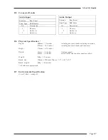
LF EQ - Maximum Gain
Adjustment:
1. Set LF Gain to maximum and select LF
. Set the audio oscillator for
80Hz and adjust LF Frequency to find the maximum level on the audio
level meter.
2. Adjust VR14 (LF Q) for +16.5dBu ±0.25dB.
3. Reset LF Gain to its centre indent position, de-select LF
and re-check
the audio level meter for 0dBu.
B.4.2 Output Balance
Equipment Required:
Calibrated audio oscillator, audio level meter and a ‘balance’ adaptor (see
below).
Test Signal:
1kHz sine wave at +24dBu.
Input and Output:
Oscillator to the Input of the channel being tested, Output to the level
meter via the ‘balance’ adaptor.
Unit Setup:
Ensure that all front panel switches are off and all controls are set fully
anti-clockwise.
Adjustment:
Connect the test equipment to the each channel in turn and adjust VR15
(BAL) for minimum level (< 55dBr).
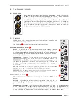
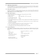
B.4.3 ‘Balance’ Adaptor
For the output balance adjustment, a ‘balance’
adaptor such as that illustrated here will be
required. This adaptor consists of a pair of close
tolerance resistors in an in-line cable and is
used to sum together a balanced output in
order to correctly adjust the level balance of the
measured output; perfect balance should result
in complete signal cancellation.
5K01**
5K01**
2
3
1
2
3
1
0V
+
–
0V
+
–
To measuring
equipment
From unit
under test
1
2
1
Resistor tolerance should ideally be 0.01%
Absolute level measured will depend upon the input
impedence of the measuring equipment.
1.
2.
Note
Summary of Contents for X-Logic
Page 1: ...X Rack Owner s Manual ...
Page 2: ......
Page 24: ...Page 20 X Rack Owner s Manual Notes ...
Page 32: ...Page B 2 X Rack Owner s Manual ...
Page 38: ...Page B 8 X Rack Owner s Manual ...