


Page B-4
X-Rack Owner’s Manual
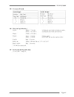
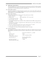
LMF Band controls:
Frequency
Variable from 200Hz to 2.5kHz
Gain
Variable by > ±20dB
‘Q’
Variable from 0.5 to 2.5 (may also vary with gain)
LF Band controls:
Frequency
Variable from 40Hz to 600Hz
Gain
Variable between ±16.5dB
‘Q’
2.5 (on ‘
’ setting)
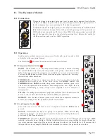
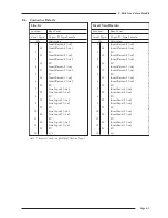
The LF and HF bands have variable turnover frequency with switchable bell/shelving and selectable
response curves:
• Normal (‘E type’) curves with the ‘G-EQ’
switch OUT follow conventional cut or
boost characteristics.
• ‘G type’ curves with the ‘G-EQ’ switch IN,
have a modified slope with a degree of
overshoot/undershoot for increased
selectivity.
The two parametric bands have selectable characteristics which affect the relationship between frequency
bandwidth and gain:
• With the ‘G-EQ’ switch OUT, the frequency
bandwidth is constant at all gains.
• With the ‘G-EQ’ switch IN, the frequency
bandwidth reduces with increased gain,
thereby increasing the selectivity of the EQ
as the gain is increased.
• At full boost or cut both are identical.
10
100
1k
10k
20k
-25.0
-20.0
-15.0
-10.0
-5.0
0.0
5.0
10.0
15.0
20.0
25.0
Amplitude (dBr) v Frequency (Hz)
Channel Equaliser Curves
’G type’
’E type’
Both
0.0
25.0
-25.0
20
100
1k
10k
100k
-20.0
-15.0
-10.0
-5.0
5.0
10.0
15.0
20.0
Amplitude (dBr) v Frequency (Hz)
Channel Equaliser Curves
’G type"
’E type’
Summary of Contents for X-Logic
Page 1: ...X Rack Owner s Manual ...
Page 2: ......
Page 24: ...Page 20 X Rack Owner s Manual Notes ...
Page 32: ...Page B 2 X Rack Owner s Manual ...
Page 38: ...Page B 8 X Rack Owner s Manual ...