background image


|

 17

January 2020 

|

 Solar Stik

®

, Inc.

Operator and Maintenance Manual for PRO-Verter RMK LAN

RMK 
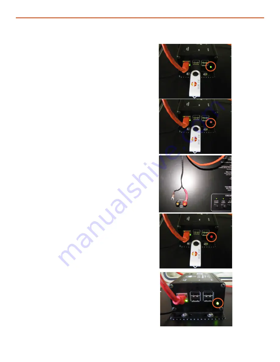
recognizing 
the USB 
drive

Uploading 
info from 
the USB 
drive 
(removed)

Cycling the 
power to 
the RMK

Setup 
complete

Figure 19. Updating the RMK’s interfaces file

When a USB drive is inserted into the RMK, 
the RMK looks for a folder with the RMK serial 
number. If one does not exist, one is created. 
The folder will be populated with log data and a 
few other files (see Figure 17). If the USB already 
contains the serial number folder, the files in this 
folder will be updated.

1.  Plug the USB drive into any of the four (4) 

USB ports; they are all equal.  The 

green

 LED 

(circled in orange) on the lower right corner 
of the RMK will turn off temporarily. 

2.  The LED will turn to 

orange

 while the RMK 

reads the interfaces file and writes any 
system data that have been logged by the 
RMK to the USB drive. This process may 
take several minutes. 

3.  When the process is finished, the LED will 

return to 

green

.  


4.  With the USB drive in the RMK and the LED 

green

, remove the NEGATIVE lead from the 

5A 24VDC post. 

5.  Reconnect the lead. The LED will turn 

red

Wait for the LED to turn 

green

. This may take 

several minutes. 

6.  Remove the USB drive. 

Updating the Interfaces File in the RMK

For the interface file changes to take effect, the 
RMK must be rebooted. This is accomplished 
by cycling the power.

The RMK is now accessible to a network at the 
reprogrammed IP address. Enter the new IP 
address into a web browser to access the interface.

Waiting for 
changes to 
take effect 
in the RMK

Note: 

The log files are extracted from the RMK onto 

the USB storage device during this process. If the 
data log files are large and numerous (Figure 8 lower 
left), this process may take a long time (up to and 
over an hour). The long wait can appear like the 
RMK is frozen. Be paitient. Do not dismount the USB 
storage device before sufficient time has been given 
for the transfer.

Summary of Contents for PRO-VERTER

Page 1: ...Solar Stik Inc OPERATOR AND MAINTENANCE MANUAL FOR PRO VERTER REMOTE MONITORING KIT LAN SS P N s 20 0702602 Version 1 0 Updated 20200106 DISTRIBUTION STATEMENT A Approved for public release distributi...

Page 2: ...10 Fault Codes and Inverter Status Codes 11 Setting a PC Static IP Address 12 Connecting the RMK to a Network via a Router 15 Files on the USB Drive Included with the System 15 Editing the Interfaces...

Page 3: ...hernet Status and Ethernet Properties windows 14 Figure 16 Internet Protocol Version 4 Properties window 14 Figure 17 List of files on the USB drive 15 Figure 18 Interfaces file 16 Figure 19 Updating...

Page 4: ...cal reports of these data in a browser based user interface Figure 1 Solar Stik PRO Verter RMK Installing the RMK 1 Install the RMK to the PRO Verter Faceplate in the designated space using the four 4...

Page 5: ...nverter Port RJ11 Crossover Cable To Remote Port 24VDC Power Port CAT5 straight through cable connects ETHERNET ports Figure 3 The RMK Ports NOTICE The cables connecting the RMK to the PRO Verter must...

Page 6: ...cable indicate a good connection If the connection is not good use a crossover cable to connect the PC to the PRO Verter 2 Configure the PC to communicate via a static IP address See Setting a PC Stat...

Page 7: ...lized S1XXX The serial number unique to that RMK will be displayed automatically in the Current Settings title All windows and values reported by the GUI are read only Figure 7 Home Screen and Current...

Page 8: ...ata from the last 24 hours The volts amps and watts are DC values Data Supplied By Inverter This is real time data from the inverter Most of the data supplied are critical component temperatures AC ou...

Page 9: ...r Charger Auto Generator Start Circuit Conditions Alarm Controls Alarm will sound with any System Fault The RMK notifies the user of fault conditions when they arise Faults include but are not limited...

Page 10: ...page that displays the information for that month in graphical form see Figure 10 Note The graphs shown here contain no real data They are shown only for the purpose of illustrating what graphs will...

Page 11: ...des Note The FAULT column Column T in log files extracted from the RMK include fault codes not listed below If fault codes other than those shown below are reported by the RMK User Interface or encoun...

Page 12: ...creen capture images show how the process appears on a Windows 10 laptop Please note that the names of the settings windows will vary based on the user s hardware installed driver for that hardware an...

Page 13: ...er RMK LAN Figure 12 Control Panel window 2 Click Network and Internet Click 3 Click Network and Sharing Center Click 4 The various active networks will appear in the window Click Ethernet Figure 13 N...

Page 14: ...he network The one in Figure 16 is set to 240 Set the other address per Figure 16 When finished click OK or Close in the three 3 windows for the changes to take effect Figure 16 Internet Protocol Vers...

Page 15: ...the interfaces file is different from the current IP address The interfaces bak file is the interfaces file that was used previously to configure the RMK Figure 17 List of files on the USB drive File...

Page 16: ...ines 4 and 5 To comment a line out place a character at the beginning of the line Lines 7 10 are used to configure an alias on the Ethernet port so that a static IP address can be used The default add...

Page 17: ...MK to the USB drive This process may take several minutes 3 When the process is finished the LED will return to green 4 With the USB drive in the RMK and the LED green remove the NEGATIVE lead from th...

Page 18: ...nk Activity Ethernet port first connected Table 2 RMK LED Indicator Guide Table 3 Link and Activity LED Meanings 4 0 Using LED Indicators to Determine MagWeb s Status 4 2 MagWeb Wired Ethernet LED Sta...

Page 19: ...he address Is the PRO Verter powered up and properly connected to the RMK Consult Connection Diagram Operating the PRO Verter without the RMK It may be necessary to use the PRO Verter without the RMK...

Page 20: ...of the RMK housing using a 2 cross tip screwdriver Figure 22 RMK on PRO Verter Faceplate Figure 23 Fastener and status LED locations Status LED I Check the DC OUT 5 A Breaker 1 The circuit supplying p...

Page 21: ...it board 4 Remove the coin cell battery and test the voltage A fully charged coin cell battery will provide 3 2 VDC If the voltage is 2 75 VDC or less it is fully discharged replace the battery and pr...

Page 22: ...ter set it to Ohms Place one lead on each of the two fuse contacts The reading will waver but remain very low m range a bad fuse will result in overload OL If the fuse is blown replace it and go to st...

Page 23: ...The card port assembly has an internal spring and makes a click when it has been unlocked Note Use insulated or nonconductive tools if possible to prevent shorting the capacitor Figure 33B Use tweezer...

Page 24: ...card B A C Users User Desktop 1049 target image 9 Interpret the results from reading the microSD card For a damaged microSD card the read process stalls indefinitely at 1 Figure 36 You may see an err...

Page 25: ...ntrol board Figure 39 Reinstalling fasteners 12 Reinstall the RMK onto the PRO Verter VI RMK Reassembly and Reinstallation V RMK Testing 13 If all tests are passed and the RMK still fails to boot when...

Page 26: ...Operator and Maintenance Manual for PRO Verter RMK LAN January 2020 Solar Stik Inc 26...

Page 27: ...ale renewable energy power generation systems with detailed explanation of system components Advanced configuration options with hands on deployment of actual systems will enhance student understandin...

Reviews: