background image

10/2022

14

EN

USER AND MAINTENANCE MANUAL

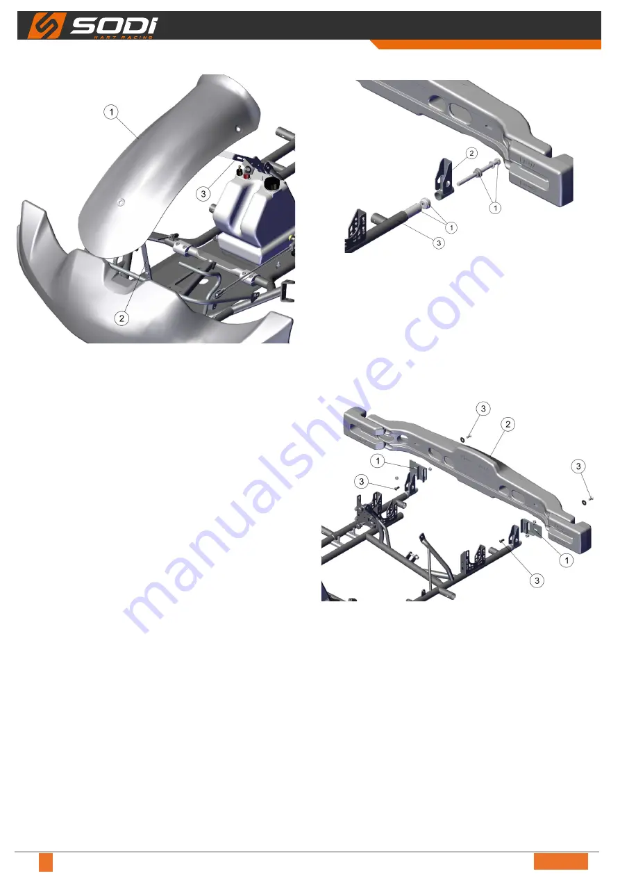
Étape 9 

Legend
1  Nassau panel

2  Lower support

3  Upper support


● Tighten the nassau panel (1) on its supports (2) and (3) 

with screws, nuts, and washers.

3.9 - Mounting the rear protections

Legend
1  Mounting kit

2  Bumper support

3  Tube chassis


● Assemble the mounting kit (1) with the element of the 

bumper support (2).


● Mount the assembly in the tube chassis (3), tighten with 

the screw of the fixing kit (1).


● Apply the same procedure for the other side.

Legend
1  Bumper support

2  Bumper

3  Screw + nut


● Assemble bumper support (1) on the bumper (2) using 

screws and nuts (3).


● Assemble the bumper (2) on the chassis with screws and 

nuts (3).

Summary of Contents for RS3 KZ DD2

Page 1: ...MAN_Sigma_EN_02 USER AND MAINTENANCE MANUAL EN ...

Page 2: ...go kart you own The document applies to all Sodikart models and includes descriptions and explanations concerning both the standard and optional equipment This means that this manual might contain some sections that do not apply to your go kart model The illustrations are used to describe the principles of assembly They are not intended to be an exact detailed representation of the go kart If you ...

Page 3: ...ustment of the brake distributor 24 5 5 1 Standard adjustment 24 5 5 2 More braking power on the front brakes 24 5 5 3 More braking power on the rear brakes 24 6 Maintenance 25 6 1 Brakes Usual maintenance 25 6 1 1 Fluids and lubricants 25 6 1 2 Frequency of cleaning and maintenance 25 6 1 3 Replacing brake pads on the D18 4 pistons callipers front 26 6 1 4 Replacing brake pads on the D20 4 piston...

Page 4: ...elf locking nuts split pins circlips and other specific parts after every disassembly Clean the contact areas from any trace of material before reassembling the parts Tighten up all fixations bolts to the specified tightening torque using a torque wrench Remove any trace of oil or grease from all threads Check the correct tightening of all parts and their functionality after reassembly To protect ...

Page 5: ...not pass This flag will be used in combination with the warning lights along the track Red flag Trouble on the track drive slowly Drive to pit lane immediately Checkered flag The driving session is finished Enter the pit lane slowly 1 3 2 Safety stickers Location 1 AC701 121 Safety instructions GB sticker 2 AC701 122 Safety instructions FR sticker 3 AC701 124 Sticker DOT 4 Meaning Summary of the m...

Page 6: ...2 Spoiler 3 Spoiler brackets 4 Nassau panel 5 Fuel tank 6 Steering wheel 7 Rims 8 Side pod 9 Left side pod bracket 10 Right side pod bracket 11 Seat 12 Seat stiffeners 13 Rear bumper At reception of your frame check the presence of all elements above For part numbers refer to the spare parts catalogue ...

Page 7: ...ket wrench 10 OU912 001 5 T shaped socket wrench 13 OU912 003 7 Brake bleeding system OU951 002 8 Socket set 1 2 22 pcs OU914 017 9 Socket set 1 4 46 pcs OU914 016 10 Tyre iron OU942 002 11 Manometer OU943 002 12 Torque wrench OU914 012 Supplied with the chassis 2 3 Maintenance products 2 1 3 5 7 4 6 8 Designations Parts N 1 DASTY cleaner degreaser LU837 051 2 MEKAONE multilube LU839 002 3 MEKAONE...

Page 8: ...ew 12 Nm M10 bleed screw 16 Nm Screws without bolts 1 drop of special glue LU861 001 Lubricate rotating parts ball joints gas cable Do not overtighten screws and bolts 3 2 Frame stabilizers Legend 1 Frame stabilizer 2 Stabilizer sleeve Always attach the stabilisers to the frame with a sleeve at each side 3 3 Positioning of the safety brake cable 1 2 Legend 1 Safety cable 2 Brake rod Always fit the...

Page 9: ... Petrol tank hose 6 Red plug Put the overflow bottle 1 on the nassau panel support 2 Connect the overflow bottle hose 3 to the return 4 Connect the petrol tank hose 5 to the red plug 6 Check the presence of the diver under the red plug 3 5 Assembly of the steering column and steering wheel See Standard adjustments p EX for the assembly dimensions corresponding to the standard setting recommended f...

Page 10: ...steering wheel support 1 on the steering column 4 Once the steering system is assembled please check that the steering wheel is free to make a quarter of a turn right and left A bad assembly or a bad adjustment of the steering system can lead to accidents Systematically check the tightening of the system and its adjustment 3 6 Assembly of the seat See Standard adjustments p EX for the assembly dim...

Page 11: ...crews and nuts references refer to the spare parts catalogue Upper end 1 2 1 Legend 1 Seat stiffener 2 Screw conical washer nut Place the upper end of the stiffener Make sure there is no contact with the exhaust system and with any part of the engine If necessary slightly bend the stiffener Drill a 8 5 mm diameter hole in the seat Place one screw conical washer 2 Tighten both upper and lower end A...

Page 12: ...to include the washers 4 Étape 2 Legend 1 Bushing 2 Screw 3 Nut Insert the bushings 1 in the nozzles on the frame Insert the assembly into the bushings 1 Drill the bushings 1 using the holes as a guide and tighten the assembly with the screws 2 and nuts 3 Étape 3 Legend 1 Lower support for Nassau panel 2 Screw 3 Nut Tighten the lower support on the frame with the screws 2 and the nuts 3 Étape 4 Le...

Page 13: ...poiler upper support 1 on the outer face of the lug 2 Tighten with the screws 3 and the nuts 4 Étape 7 Legend 1 Mounting flange spoiler 2 Upper support 3 Lower support 4 Screw 5 Nut Assemble the mounting flange spoiler 1 between the spoiler upper support 2 and the spoiler lower support 3 with two screws 4 and two nuts 5 Étape 8 Legend 1 Spoiler 2 Upper support 3 Lower support 4 Clamp Place the spo...

Page 14: ...egend 1 Mounting kit 2 Bumper support 3 Tube chassis Assemble the mounting kit 1 with the element of the bumper support 2 Mount the assembly in the tube chassis 3 tighten with the screw of the fixing kit 1 Apply the same procedure for the other side Legend 1 Bumper support 2 Bumper 3 Screw nut Assemble bumper support 1 on the bumper 2 using screws and nuts 3 Assemble the bumper 2 on the chassis wi...

Page 15: ...CIK FIA regulations Compulsory Suit CIK FIA level 1 or level 2 approved Compulsory Gloves Compulsory Neck protection CIK FIA approved Compulsory Rib protection fitting pilot s size and seat Recommended Rain suit with water tight fasteners Recommended when necessary Choose those equipment within the CIK FIA approved ones of the ITAKA web site Driving is forbidden to any pilot Wearing a scarf becaus...

Page 16: ...ngs inside 10 mm B 90 mm Sigma KZ DD2 A 3 rings inside 15 mm B 90 mm Sigma RS KZ DD2 A 4 rings inside 20 mm B 90 mm Rear tracking width A Sigma RS A 1 390 mm to 1 400 mm Sigma KZ DD2 A 1 400 mm Sigma RS A 1 360 mm to 1 380 mm Sigma KZ DD2 A 1 370 mm to 1 380 mm Rear axle position A B C Sigma RS KZ DD2 B Medium Sigma RS B Medium Sigma KZ DD2 B High Position of eccentrics 1 A 1 Front Front C B Sigma...

Page 17: ...40 mm 10 mm Sigma KZ DD2 A Lower face of the tubes 0 mm B 1 045 mm 10 mm Sigma RS A Lower face of the tubes 0 mm B 1 040 mm 10 mm Sigma KZ DD2 A Lower face of the tubes 0 mm B 1 060 mm 10 mm Seat stiffeners A B Sigma RS Left side A 2 Right side B 1 Sigma KZ Left side A 2 Right side B 2 Sigma DD2 Left side A 1 Right side B 0 Sigma RS Left side A 2 Right side B 1 Sigma KZ Left side A 2 Right side B ...

Page 18: ...re than a 20 mm spacer A 1 spacer of 15 mm and 1 spacer of 5 mm on the yoke side on each stub axle if the kart is equipped with front brake Wet track without front brake A B It is advisable to adjust the front with a spacer of 25 mm A 1 spacer of 15 mm and 2 spacers of 5 mm inside and use the long hub 100 mm B Wet track with front brake A B It is advisable to adjust the front train with a spacer o...

Page 19: ...ned on the opposite side of the screw towards the rear of the chassis Adjustment of the caster Low FRONT REAR Eccentrics on top The mark is positioned on the opposite side of the screw towards the rear of the chassis Eccentrics on bottom The mark is positioned in front of the screw towards the front of the chassis Standard adjustment 1 upper eccentrics placed in high caster position Increase the c...

Page 20: ... the chassis Camber More negative Front Rear 1 1 Eccentrics at the bottom The mark is positioned towards the inside of the chassis Standard adjustment 1 lower eccentrics place in negative camber position Increase the camber Same position as the Camber More negative p 20 but replace the lower 1 eccentric by the 2 eccentric Reduce the camber Same position as the Camber More positive p 20 If eccentri...

Page 21: ... 2 5 Quick adjustment of caster camber pill 1 Remove both screws 2 Unlock axle of the front stub 3 Rotate the 2 caster camber pills to adjust the caster or camber angle Adjustments Caster angle Top caster camber pill Camber angle Low caster camber pill ...

Page 22: ...stub axle in position 4 measure the dimension C Turn the wheels in the opposite direction and measure the dimension C for the second wheel The two dimensions C must be equal Recommended setting on a dry track 2 mm opening B A 2 mm Make sure the dimensions C are equal on each side Recommended setting on a wet track 7 mm opening B A 7 mm Make sure the dimensions C are equal on each side Remove the f...

Page 23: ...s too wide it tends to increase sliding If the rear tracking width is too narrow it leads to a bumpy chassis Badly tightened wheels may lead to severe even fatal injuries Check that the hub key 5 is correctly positioned Never position the hubs beyond the maximum allowed width it may lead to severe or even fatal injuries 5 3 2 Position of rear axle On most tracks the correct axle position is the mi...

Page 24: ... very high grip conditions 4 Seat higher Increases the grip To be tried in wet conditions Always use a seat tightener One on the left hand side and one on the right hand side give an optimal performance on almost all types of tracks 5 5 Adjustment of the brake distributor The brake distributor allow to monitor the bracking power between the front and rear brakes 2 4 1 5 3 Legend 1 Handle 2 Brake d...

Page 25: ...ef LU823 004 Use brake fluid DOT 4 only Using another brake fluid could cause leaks and failure of the brake system The brake system is not compatible with DOT 5 Place the fluids in watertight cans and recycle them according to the regulations in force Never spray brake cleaner on the master cylinder and brake calliper seals 6 1 2 Frequency of cleaning and maintenance Before any session After 1 me...

Page 26: ...callipers rear 2 3 5 4 1 4 Nm Loctite 648 Legend 1 Adjustment screw 2 Return screw 3 Spring 4 Pin 5 Brake pad Adjust the brake pads until they reach the stop using the adjustment screws 1 Remove the four return screws 2 and the four springs 3 Straighten the ends of the pin 4 and then remove it Remove the used brake pads 5 Place the new pads 5 in position Place the new pin 4 in position and then tw...

Page 27: ...u have the slightest doubt do not put the kart in service 6 1 6 Adjusting the gap between the pads and the disc 1 3 1 3 2 1 mm 1 mm Legend 1 Adjustment screw 2 Disc 3 Pad Tighten or loosen the screw 1 to obtain a 1 mm gap between the disc 2 and the pad 3 6 1 7 Replacing the brake hose The brake fluid hoses are a critical safety element It is very important to check their state regularly Check the ...

Page 28: ... no air bubbles Retighten the calliper bleed screw 1 remove the pipe and reapply the protective cap Repeat the operation for the front left calliper Niveau Max Max Level Top up the brake fluid in the master cylinder to its maximum level and retighten the cap 2 and the diaphragm 4 An air bubble in the brake system can lead to a partial or total lost of brake and may lead to a serious or even fatal ...

Page 29: ...s Retighten the calliper bleed screw 1 remove the pipe and reapply the protective cap Top up the fluid in the master cylinder to its maximum level and retighten the cap 2 and the diaphragm 3 An air bubble in the brake system can lead to a partial or total loss of brake and may lead to a serious or even fatal injury Leaks in the brake system may lead to a serious or even fatal injury Moisture in th...

Page 30: ...er seals 6 2 Brakes Workshop maintenance 6 2 1 Replacing calliper seals 4 pistons calliper D18 front This operation must be performed by a SODIKART dealer Removing 2 3 4 1 Legend 1 Pin 2 Brake pad 3 Bleeder screw 4 Mounting screw Untwist the ends of the pin 1 and remove it Remove the brake pads 2 Remove the bleed screw 3 and its cap Disconnect the yoke by removing the two mounting screws 4 2 1 3 L...

Page 31: ...ce the O rings 6 in position and then connect the two half callipers 1 2 Loctite 268 12 Nm 15 Nm x3 Legend 1 Bleeder screw 2 Mounting screw Apply three drops 120 apart of loctite alongside the screw thread 2 Tighten the two screws 2 Torque 15 Nm Tighten the bleed screw and its cap 1 Torque 12 Nm Clean the brake fluid on the bleed screws Reinstall brake pads refer to Replacing brake pads on the D18...

Page 32: ...rew 6 and its cap Disconnect the yoke by removing the two mounting screws 7 8 9 10 Legend 8 O ring 9 Piston 10 Gasket Remove the two O rings 8 the two pistons 9 and the two seals 10 from each half calliper 12 11 13 Legend 11 Clip 12 Piston stop 13 O ring Remove the piston stop clip 11 using fine pliers or a scriber Loosen the piston stop 12 and remove the O ring 13 Apply the same procedure for the...

Page 33: ...e tool 4 2 1 2 Legend 1 Clip 2 Piston stop Place the piston stop clip 1 in the groove of the piston stop 2 Check that the piston stop clip 1 is correctly clipped in the groove of the piston stop 2 IMPORTANT To ensure that the clip is positioned on the piston stop loosen the stop it should not leave the calliper body 1 2 PFG110 3 4 Legend 1 O ring 2 Piston 3 Gasket 4 Groove Apply PFG110 grease to t...

Page 34: ... pads after any servicing of the callipers 6 2 3 Replacing calliper seals 2 pistons calliper D28 rear This operation must be performed by a SODIKART dealer Removing Legend 1 Pin 2 Brake pad 3 Bleeder screw x2 4 Mounting screw 5 Silicon hose Untwist the ends of the pin 1 and remove it Remove the brake pads 2 Remove the bleed screws 3 and their caps Disconnect the yoke by removing the two mounting s...

Page 35: ...que 16 Nm Clean the brake fluid on the bleed screws Reinstall brake pads refer to Replacing brake pads on the D28 2 pistons callipers rear p 27 Always use new seals and clips Replace any defective parts using only original SODIKART parts Install a new set of pads after any servicing of the callipers 6 2 4 Replacing master cylinder seals and pistons This operation must be performed by a SODIKART de...

Page 36: ...et 2 and the seal 3 Place the gasket 2 in the piston groove 1 Install the seal 3 on the piston 1 Apply PFG110 grease to the gasket 2 the seal 3 and the piston 1 1 4 2 3 Legend 1 Pressure pin 2 Dust cover 3 Pin 4 Piston lever Reinstall the piston lever assembly 4 in the master cylinder Reinstall the pin 3 Reinstall the dust cover 2 and pressure pins 1 on the master cylinder Always use new seals Rep...

Page 37: ...than 4 bars Excessive wear of tyres can result from bad front wheel axle unit alignment Use tyres with a grip adapted to your track Give worn tyres to a specialist of tyre treatment according to local environmental regulation Change all damaged rims A damaged rim may lead to a loss of tyre or loss of pressure and may lead to a serious or even fatal injury Check the tyre wear daily Worn or damaged ...

Page 38: ...ar wheel bolts Rear wheel hub screws Engine support screws Seat screws Damaged screws and bolts have to be changed 6 5 2 Steering Check daily the upper and lower column plastic support torque as well as stub axle screws Make sure that front wheel axle unit is not out of line stub axles bent or broken Check that the tie rods are not damaged 6 5 3 Bodywork parts Parts of the bodywork must not be bro...

Page 39: ... Is the front axle unit checked 7 4 The steering of the kart is not precise 1 Are the front wheels tightened 2 Are the stub axles tightened to torque specification 3 Are the column plastic supports tightened to torque specification 4 Are the tie rods correctly assembled and to torque specification 5 Is the front wheel axle unit adjustment checked 7 5 The kart tends to go to the side 1 Is the front...

Page 40: ...tor 24 E Eccentric 19 20 F Fastener clip 9 Frame 6 Front wheel alignment 22 Fuel tank 6 9 G Gasket 31 32 33 35 Grease 25 H Hose 38 Hub 23 M Maintenance products 7 Manometer 7 Master cylinder 35 N Nassau 6 9 12 14 O O ring 31 32 33 35 Overflow bottle 9 P Pad 27 PFG110 grease 7 Piston 26 27 31 32 33 35 Plug 9 R Rear bumper 6 Rims 6 S Seat 6 10 Side pod 6 12 Side pod support 12 Spoiler 6 12 Stabilize...

Page 41: ...MAN_Sigma_EN_02 USER AND MAINTENANCE MANUAL 41 EN 9 Homologation ...

Page 42: ...10 2022 42 EN USER AND MAINTENANCE MANUAL ...

Page 43: ...MAN_Sigma_EN_02 USER AND MAINTENANCE MANUAL 43 EN ...

Page 44: ...10 2022 44 EN USER AND MAINTENANCE MANUAL ...

Page 45: ...MAN_Sigma_EN_02 USER AND MAINTENANCE MANUAL 45 EN ...

Page 46: ...10 2022 46 EN USER AND MAINTENANCE MANUAL ...

Page 47: ...MAN_Sigma_EN_02 USER AND MAINTENANCE MANUAL 47 EN ...

Page 48: ...10 2022 48 EN USER AND MAINTENANCE MANUAL ...

Page 49: ...MAN_Sigma_EN_02 USER AND MAINTENANCE MANUAL 49 EN ...

Page 50: ... width Pressure arrival Lap Partial 1 Partial 2 Partial 3 Partial 4 1 2 3 4 5 6 7 8 9 10 Notes ENGINE Carburator type Adjustments Exhaust type Gear ratio Length Chain length CHASSIS Stub axle height Caster Camber Parallelism Seat position Height Distance axle Distance fork Masses Axle type Stiffeners 1 2 3 4 1 2 3 4 1 2 3 4 1 2 3 4 1 2 3 4 1 2 3 4 1 2 3 4 1 2 3 4 ...

Reviews: