13
EN
AP8. TEMPERATURE MODE
This section explains how to configure the
“TEMPERATURE”
control mode. This mode allows the drive to regulate the
speed of the ventilator as well as the warm or cold air inlet through a frequency inverter VSD*/A depending on the
temperature detected by the analogic sensor. Inverter starting is done from an external control (selector).
8.1 PROGRAMMING
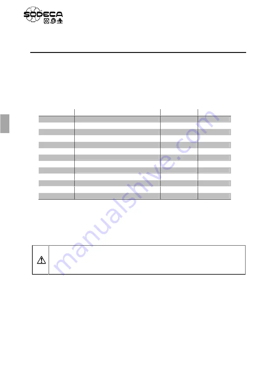
Use the next table to change to, or modify, the TEMPERATURE mode.
Table “TEMPERATURE”
1.
In order to make the regulation more dynamic, change the
o
parameters. Increase
until the output
is fast enough. The increase
as much as possible and stop before the system oscillates.
2.
If we need warm air inlet we should configure
to 0, on the contrary, if we need cold air inlet we should
configure to 1
.
3.
See sections 8.2 and 8.3 for the setpoint configuration.
8.2 PROBE SI-TEMP IND CONFIGURATION
Is recommended to adjust the output signal to 0-10V and the sensor SI-TEMP IND measuring scale.
This adjustment by
means of the jumpers JP1 and JP2 respectively. Remove the cover of the probe to find this jumpers. (
See Fig. 15).
Parameter
Description
Adjustment
Units
Maximum Frequency
50.0
Hz
Minimum Frequency
20.0
Hz
Acceleration Ramp Time
5
s
Deceleration Ramp Time
5
s
Motor Rated Current
x.x
A
Primary Command Source
5
Extended Menu Access code
101
Analog Input 1 Signal format
U 0-10
V
PI Controller Proportional Gain
0.2
%
PI Controller Integral Time
1.0
s
PI Controller Operating Mode
0 - 1
PI Digital Setpoint
xx.x
%
PI Feedback Source Select
1
ATTENTION:
If there’s a power loss while the ventilator is working and the RUN switch is
closed, the drive will enter the stop stage and show
on the display. Once the power is
restored, if the RUN switch is still closed, the drive will maintain the stop status. In order to start
again, the RUN switch must be opened and closed again. This operation can be modified
setting the
mode in the
parameter.
Summary of Contents for VSD/A
Page 2: ......
Page 3: ...Fig 6 Fig 9 VSD A...


