35
CPSS Emergency MASTERYS EM
10 to 80 kVA - Ref.: IOMMASELXX03-GB 00
• Residual capacity
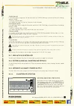
In the Residual capacity confi guration, the load connected to the POWER SHARE plug is disconnected if one of the following
conditions is verifi ed:
- One of the standard conditions.
- The residual battery capacity is lower than the value set on the mimic panel.
• Remaining backup time
In the remaining backup time confi guration the load connected to the POWER SHARE plug is disconnected if one of the following
conditions is verifi ed:
- One of the standard conditions is verifi ed.
- The residual battery backup time is lower than the value set on the mimic panel.
• Emergency lighting
In an emergency lighting confi guration the load connected to the POWER SHARE plug operates with inverse logic, i.e. it is con-
nected if the following condition is verifi ed: the mains is not present.
The time taken to activate the power share plug is, according to the EN50171 standard, average activation time
(delay between 0.5 and 15 seconds) .
• Time after failure
With the NET-VISION option only, the shutdown of the load connected can be programmed in accordance with the UPS backup
time. On return of the nominal mains parameters, the plug operating conditions are restored.
If the UPS is out of service the power share plug still powers the load connected to it by operating in permanent
configuration.
The load connected to the power share plug is always powered, regardless of the configuration selected.
Maximum current that can be drawn from the power share terminals: 16 A 250 VAC Ac3 3-phase.
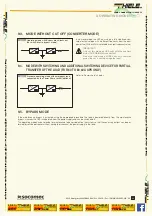
10.7. INSULATION CONTROLLER
This device continually checks transformer insulation, displaying an alarm message on the mimic panel.
10.8. EXTERNAL MANUAL MAINTENANCE BYPASS
This device will electrically exclude and isolate the UPS (e.g. for maintenance operations) without interrupting the power supplied
to the load.
10.9. SEPARATE AUXILIARY POWER SUPPLY
This allows the use of an auxiliary energy source other than the primary mains power supply in the event of outage.
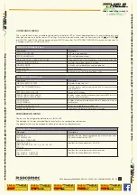
10.10. BACKFEED
PROTECTION
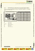
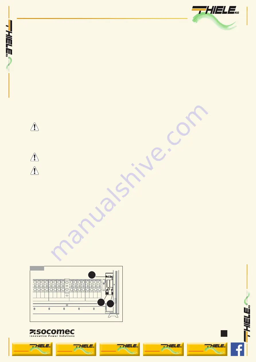
EXTERNAL BACKFEED PROTECTION
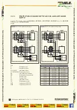
External devices can be installed to protect against the back-
feed of dangerous currents, both on the
MAINS SUPPLY
and
on the
AUX MAINS SUPPLY
. These devices are controlled by
the
BKF PCB
installed in the position shown in figure below.
Refer to the following paragraphs for details on electrical
connections and on activating the chosen protection.
O
UT
P
UT
L12 L22 L
3
2
N
2
EXTE
RNA
L
BA
TTE
R
Y
+
B
2
–
B
2
–
B
1
+
B
1
A
UX
MA
I
NS
S
U
PP
LY
L11 L21 L
3
1
N
1
MA
I
NS
S
U
PP
LY
L1 L2 L
3 N
XC1
XB2
XB1
10.10-1
10. STANDARD FEATURES AND OPTIONS
YOUR CONNECTION TO SAFETY
Thiele KG
• V
orderer W
einberg 26 • D-71522 Backnang • T
el.: +49 (0)7191 3560-0
• Fax.: +49 (0)7191 3560-19
• www
.thiele-kg.de
Thiele KG
• V
orderer W
einberg 26 • D-71522 Backnang • T
el.: +49 (0)7191 3560-0
• Fax.: +49 (0)7191 3560-19
• www
.thiele-kg.de
YOUR CONNECTION TO SAFETY
klick to
www
u-s-v
YOUR CONNECTION TO SAFETY
klick to
www
ACDC-DCDC
YOUR CONNECTION TO SAFETY
klick to
www
SYSTEME
YOUR CONNECTION TO SAFETY
klick to
www
CONTACT
YOUR CONNECTION TO SAFETY
klick to
www
CALLBACK

