

19
ENGLISH
MASTERYS BC
15-40 kVA - Ref.: IOMMASBCXX09-EN 01
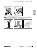
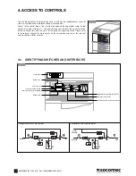
2. UNPACKING AND INSTALLATION OF THE UNIT
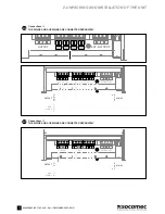
2.11-1
L12 L22 L32
N2
L11
L1
L21
L2
L31
L3
N11
N1
+B2 -B2 -B1 +B1
EXTERNAL BATTERY
+B2 –B2 –B1 +B1
EXT. BATTERY
OUTPUT
MAINS SUPPLY
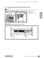
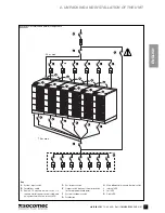
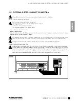
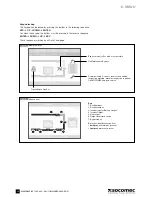
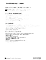
2.11. EXTERNAL BATTERY CABINET CONNECTION
If the UPS has internal batteries connecting external battery cabinets is prohibited.
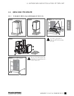
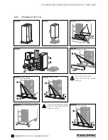
Position the battery cabinet next to the UPS.
Before carrying out any operations ensure that:
• the battery fuses located inside the battery cabinet are open;
• the UPS is not live;
• all mains or battery switches are open;
• the switches upstream of the UPS are open.
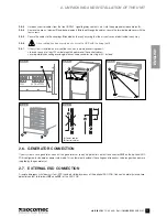
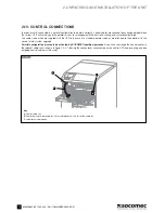
• Remove the terminal board protection.
• Connect the ground cable.
• Connect the cables between the UPS terminals and the battery cabinet terminals, strictly observing the polarity of each individual
string and the cross-sections indicated in table 2.4.
Use double insulated cables or the cables supplied with the unit to connect the UPS to the battery cabinet. The
length L of battery cable must not be more than 8 metres long (if L > 8 m, please contact the support service).
Cabling errors with inversion of battery polarity may cause permanent damage to the equipment.
• Replace the terminal board’s protection.
If using cabinets not supplied by the UPS manufacturer, it is the installer’s responsibility to check the electrical compa-
tibility and presence of appropriate protection devices between the UPS and the battery cabinet (fuses and switches
of sufficient capacity to protect the cables from the UPS to the battery cabinet). As soon as the UPS is switched on
(before closing the battery switches) the battery parameters must be verified accordingly (voltage, capacity, number
of elements, etc.) on the mimic panel menu. If the values indicated on the battery cabinet data plate are different from
those shown on the mimic panel use the SERVICE > CONFIGURATIONS menu to correct the settings.
UPS
BATTERY CABINET


