


11
ENGLISH
MASTERYS BC
15-40 kVA - Ref.: IOMMASBCXX09-EN 01
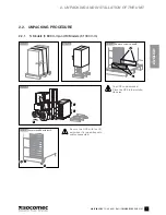
2. UNPACKING AND INSTALLATION OF THE UNIT
2.4. ELECTRICAL
REQUIREMENTS
The installation and system must comply with national plant regulations.
The electrical distribution panel must have a protection and sectioning system installed for the input mains and the auxiliary mains.
If a differential switch is installed on the mains power switch (optional), it must be inserted upstream from the distribution panel.
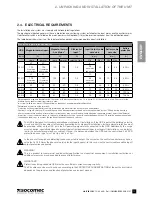
The table below shows the size of the input protection devices recommended for correct installation.
Size of the input protection devices
UPS
Magneto-thermal input
1
Magneto-thermal
Aux Mains
1
Diff erential
input
5
Input/Output cable
core size
Battery cable
core size
Battery
protection
4
(kVA)
(A)
(A)
(A)
(mm
2
)
(mm
2
)
(A)
single
parallel
2
single
parallel
2
selective type
5
Min
Max
3
Min
Max
3
15 3/1
32
40
100
125
0.5
6
35
6
35
50 Gr
100
if common
input mains
125
if common
input mains
25
aux mains
and outpu
t
20 3/1
40
63
125
160
0.5
10
35
10
35
63 Gr
125
if common
input mains
160
if common
input mains
35
aux mains
and output
15 3/3
32
40
32
40
0.5
6
35
6
35
50 Gr
20 3/3
40
63
40
63
0.5
10
35
10
35
63 Gr
30 3/3
63
80
63
80
0.5
16
35
16
35
100 Gr
40 3/3
80
100
80
100
0.5
25
35
25
35
125 Gr
1
Recommended magneto thermal switch: four poles with intervention threshold ≥ 10 In (curve C). It is necessary to use a D curve selective
breaker if an optional external transformer is used.
2
In systems with two or more UPSs operating in a redundant or power parallel confi guration.
3
Determined by the size of the terminals.
4
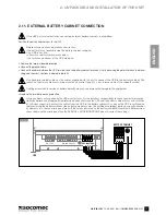
Protection on the external battery cabinet (preferably 2 bipolar protection devices or one quadripolar).
5
Caution! Use type B selective (S) circuit breakers. Load leakage currents are added to those generated by the UPS and during transitory
phases (power failure and power return) short current peaks may occur. If loads with high leakage current are present, adjust the diff erential
protection. It is advisable in all cases to carry out a preliminary check on the earth current leakage with the UPS installed and operational with
the defi nitive load, so as to prevent the sudden activation of the above switches.
The UPS is designed for transitory overvoltages in category II installations. If the UPS is part of the building’s electric
circuit or is likely to be subject to transitory overvoltages in category III installations, further external protection must
be provided, either on the UPS or in the AC power supply network connected to the UPS. Additionally, the ‘surge
arrestor’ option, specially designed to protect against residual overvoltages in category III installations, can be instal-
led in the external manual bypass cabinet. If used, the distance between the UPS and the centralised 4 kV SPD
protection device type 1 must be Up ≤ 4kV is ≥ 15m.
In the event of three-phase distorting loads connected in output, the current on the neutral conductor may have a
value that is 1.5-2 times the phase value (also for the input bypass). In this case, size the neutral cables and the input/
output protection adequately.
WARNING!
This is a product for commercial and industrial application in an industrial environment - installation restrictions or
additional measures may be needed to prevent interference.
IMPORTANT!
Protective earthing conductor (PE) must have sufficient current-carrying capacity.
The PE cable core size must be chosen according to the PROTECTIVE CURRENT RATING of the earth circuit which
depends on the provision and location of protective overcurrent devices.


