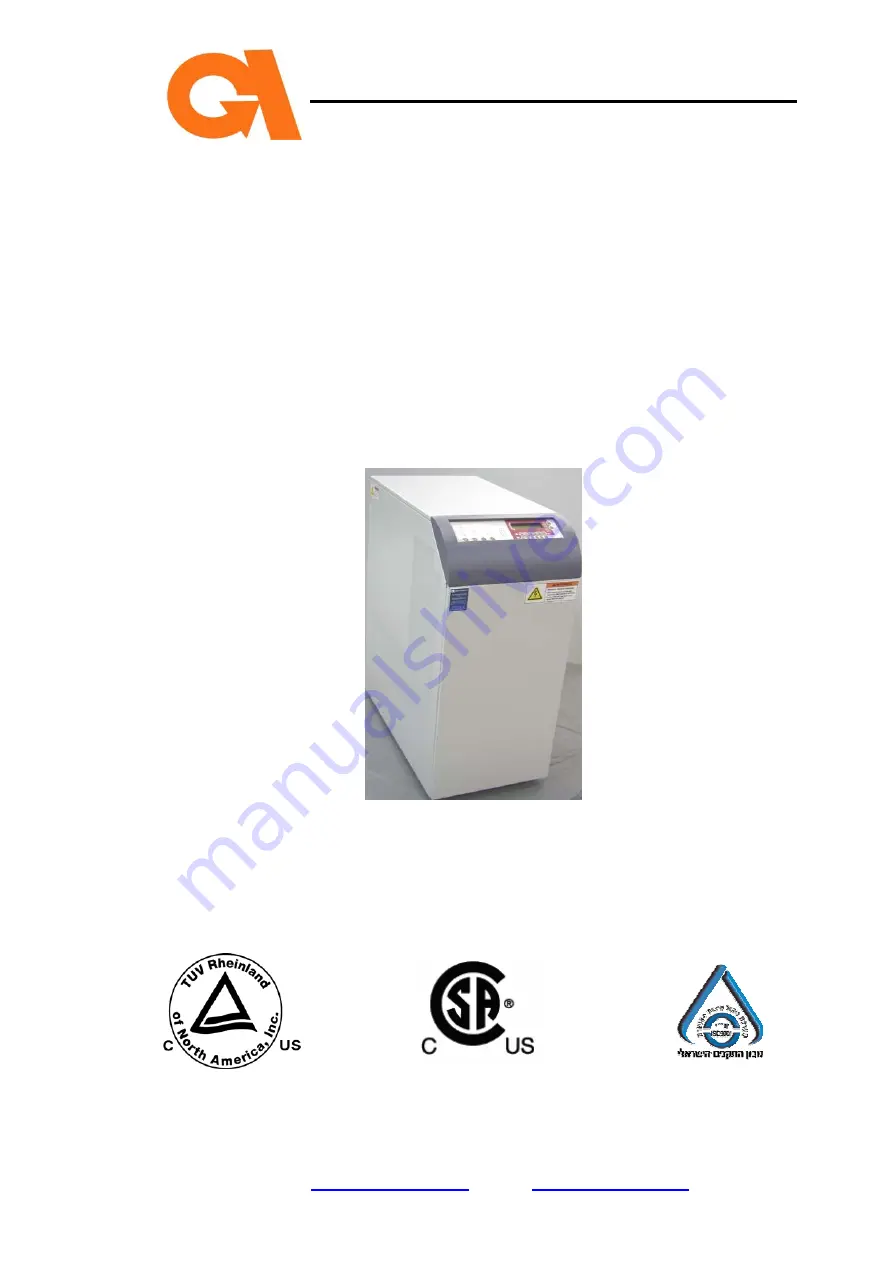
manualshive.com logo in svg
background image


Gamatronic Electronic Industries Ltd.


Har Hotzvim Industrial Park,  

14 Hartum St., P.O.B. 45029, Jerusalem 97774, Israel 

Tel:  972-2-588-8222     Fax: 972-2-582-8875 

Email:  

[email protected]

     web:  

www.gamatronic.com


µPS Series 3:3 Phase  

10

K

VA


(GEMS) 


User Guide and Instruction Manual 


Release 3.13 

October 2004 


Содержание uPS 3:3 Phase Series

Страница 1: ...im Industrial Park 14 Hartum St P O B 45029 Jerusalem 97774 Israel Tel 972 2 588 8222 Fax 972 2 582 8875 Email info gamatronic co il web www gamatronic com PS Series 3 3 Phase 10KVA GEMS User Guide an...

Страница 2: ...tice or liability to make changes in equipment design or specifications Information supplied by Gamatronic Electronic Industries Ltd is believed to be accurate and reliable However no responsibility i...

Страница 3: ...ng 10 3 2 4 Seismic Anchoring Kit Optional 10 3 2 5 UPS Communications Optional 12 3 3 INSTALLATION PROCESS 12 3 3 1 External Inspection 13 3 3 2 Seismic Anchoring Optional 14 3 3 3 Preparation for In...

Страница 4: ...Bracket 17 Figure 12 Front Mounting Bracket 17 Figure 13 Rear Mounting Bracket 18 Figure 14 Bracket Cover 18 Figure 15 UPS Circuit Breakers with Protective Covers 19 Figure 16 Terminal Connections wi...

Страница 5: ...Do not try to repair it yourself Use the UPS only for its intended purpose WARNING RISK OF LETHAL ELECTRIC SHOCK The battery cabinet contains a series of 12 Volt batteries that provide high voltage a...

Страница 6: ...e The UPS operates on line and once activated provides voltages of 3 208Vac at a stabilized 50 or 60 Hz frequency depending upon your configuration to load When backup service is provided upon mains p...

Страница 7: ...ge driver PC968 card an L C filter circuit isolated output transformer circuit current transformer PC075 card and a PC871 PWM control card 2 1 4 Static Switch ST SW BYPASS The ST SW bypass transfers t...

Страница 8: ...that enable the user to effectively manage the UPS Once the UPS is installed the control panel serves as the user s primary interface with the system Messages warnings and error conditions are relayed...

Страница 9: ...ions port to a host computer or using a modem connected to a telephone line to a remote location 2 7 Log The system compiles a listing of up to 200 extraordinary events of the mains unit and load duri...

Страница 10: ...ician s SERVICE MODE that is password protected Access to the service mode is permitted only after the technician successfully enters the correct password 2 11 Connections The terminal connectors are...

Страница 11: ...Gamatronic Electronic Industries Ltd User Guide Page 7 PS Series 3 3 Phase 10kVA GEMS Figure 4 Schematic Drawing...

Страница 12: ...ot try to repair it yourself WARNING RISK OF LETHAL ELECTRIC SHOCK The battery cabinet contains a series of 12V batteries that provide high voltage and energy in the UPS body even when the UPS is not...

Страница 13: ...tion Considerations 1 Use the shortest possible output distribution cable runs at the installation site consistent with logical equipment arrangements and in compliance with NEC and local electrical c...

Страница 14: ...vidual separate conduit or cable tray Verify that control wiring is run in an individual separate conduit 2 For minimum conductor size refer to Table 2 on page 11 which has been prepared in accordance...

Страница 15: ...ions 6 All power should be turned OFF before any cables or wires are installed or connected A qualified individual should check to ensure that the power is OFF 7 Power and control wires must be separa...

Страница 16: ...on Process Only an authorized electrician may perform installation Do not attempt to perform any of the following instructions on your own Electrical codes may vary according to location Observe all l...

Страница 17: ...arent If any damage is noted file a damage claim with the shipping agency within 24 hours and contact your Gamatronic authorized service representative to inform them of the damage claim and the condi...

Страница 18: ...Kit Parts and Figure 8 UPS Holder Table 3 Seismic Anchoring Kit Parts List ITEM PART NAME QTY PART NO CATALOG NO 1 UPS Rear Mounting Bracket 1 GE UPS 10kVA 40 00 2MCM510QJ 2 Rear Angle Bracket 1 GE U...

Страница 19: ...Seismic Anchoring Kit Parts To install the seismic anchoring kit 1 Attach the UPS holder item 3 to the front of the UPS using two 5 16 hex bolts item 6 See Figure 8 Figure 8 UPS Holder 2 Attach the r...

Страница 20: ...ge 16 Figure 9 Rear Angle Bracket 3 Attach the front mounting bracket item 4 to the UPS holder using two 5 16 hex bolts item 6 See Figure 10 Figure 10 Front Mounting Bracket 4 Attach the rear mounting...

Страница 21: ...nting Bracket and Rear Angle Bracket 5 Position the UPS in its final location 6 Drill an11mm hole in the floor at the location of each anchor bolt Drill bit not included 7 Bolt the front mounting brac...

Страница 22: ...age 18 8 Bolt the rear mounting bracket to the floor using 3 8 expansion anchor bolts item 15 See Figure 13 Figure 13 Rear Mounting Bracket 9 Attach the bracket cover item 5 to the front mounting brac...

Страница 23: ...tic Switch OUTPUT BATTERY C B in horizontal position MAINTENANCE BYPASS covered by a separate metal plate Verify that ALL the circuit breakers are turned OFF and that the protective covers have not be...

Страница 24: ...Cover 3 Terminals are located on the back of the UPS unit Remove the protective cover shown in Figure 16 4 Connect the UPS unit wiring as shown in Figure 17 using the grades of wire specified in Table...

Страница 25: ...cable through the center cable holder PG29 shown in Figure 17 Refer to Table 4 for dimension details 7 For EPO connection run the cable through the cable holder on the right PG16 shown in Figure 17 Re...

Страница 26: ...ower connections are tight 5 Verify that all control wire terminations are tight 6 Verify that all power wires and connections have proper spacing between exposed surfaces phase to phase and phase to...

Страница 27: ...their protective cover intact Note The Auxiliary switch located next to the MAINTENANCE BYPASS functions as a safety circuit breaker In the event that both the MAINTENANCE BYPASS and INPUT CHARGER cir...

Страница 28: ...tries Ltd PS Series 3 3 Phase 10kVA GEMS Page 24 DO NOT ATTEMPT TO SWITCH THE UPS ON TO OPERATE THE UPS After installation is complete contact your Gamatronic authorized service representative to sche...

Страница 29: ...round function buttons for controlling the unit and 12 square information buttons for monitoring the UPS status Text information is displayed on the LCD and may be emphasized with audible alerts to no...

Страница 30: ...between inverter and bypass signals Constant updating of display panel information Memory RAM EPROM EEPROM Real time clock Analog digital converters Keyboard Interface chip Modem connection and config...

Страница 31: ...fault remains lit to continue to alert you until the problem is resolved BATTERY TEST The unit automatically and continuously checks the battery connection with the UPS Additionally battery checks are...

Страница 32: ...battery backup 4 3 Information Buttons The UPS continually monitors its operational status The user can view real time information on the LCD by pressing the appropriate information button Information...

Страница 33: ...e IN button to display the unit s real time Input Voltage status B P Bypass Press the B P button to display the unit s bypass output voltage and current Note The bypass display will show current value...

Страница 34: ...frequency is determined by the quartz oscillator and should be set at 50 60 Hz BATT Battery Press the BATT button to display the battery voltage TIME Press the TIME button to display the system curren...

Страница 35: ...up to 200 events Press the LOG button to enter Log mode Press the arrow buttons to scroll through the log information SET Time Mode Sets the unit s real time clock Refer to Section 5 2 of this manual...

Страница 36: ...rs LED indicators provide information at a glance regarding the UPS s status or operation They are color coded so that the user can quickly and easily identify areas of concern Red indicates a fault o...

Страница 37: ...en B P UPS connected to the Bypass Battery backup not available Red OVERLOAD Overloaded output Red BATTERY Batteries have low voltage or are disconnected Red SYNC Synchronized inverter Green CHARGER C...

Страница 38: ...as instructed Follow prompts on the Advisory Display Turning ON one or more of the switches too soon or in the wrong sequence may result in system failure and or loss of power to the load 5 1 1 To tu...

Страница 39: ...to appear on the LCD display panel Verify that the green INV LED is lit on the control panel If there is no mains or bypass input INPUT FAULT appears on the LCD display panel If the bypass condition...

Страница 40: ...e TIME button to enter the time mode The normal TIME display is shown on the LCD panel 2 Press the SET button to initiate the time setting mode Note that the flashing field indicator automatically pos...

Страница 41: ...it breaker on the back of the UPS 10 Turn OFF the OUTPUT circuit breaker on the back of the UPS 11 Press twice on the UPS OFF button on the control panel on the front of the UPS 12 Turn OFF the ST SW...

Страница 42: ...y contain an Emergency Power Off EPO switch connected to the UPS If such a switch is installed and connected to the UPS s special dry contacts you can press this external switch in the event of an eme...

Страница 43: ...39 PS Series 3 3 Phase 10kVA GEMS 26 Wait approximately 40 seconds for UPS OK to appear on the LCD display panel Verify that the green INV LED on the control panel is lit If there is no mains or bypas...

Страница 44: ...computer with dedicated software Remote control through an SNMP WEB management program for computer network communications Figure 20 Local Direct Connection 6 1 RS232 Interface The UPS supports stand...

Страница 45: ...tries Ltd User Guide Page 41 PS Series 3 3 Phase 10kVA GEMS Communications parameters 2400 Baud rate No parity 1 stop bit No flow control 1 5 6 9 Rx Tx COM RS232 Table 6 RS232 Connector Pin Assignment...

Страница 46: ...User Guide Gamatronic Electronic Industries Ltd PS Series 3 3 Phase 10kVA GEMS Page 42 7 ALARM INTERFACE The following diagram describes the alarm interface Figure 21 Alarm Interface...

Страница 47: ...r to bypass and then back to inverter Takes approx 40 sec LOAD TRANSFERING PLEASE WAIT Displayed for more than 3 sec Load on B P INV LED is not lit Defective Inverter Call service technician INVERTER...

Страница 48: ...User Guide Gamatronic Electronic Industries Ltd PS Series 3 3 Phase 10kVA GEMS Page 44...

Страница 49: ...Gamatronic Electronic Industries Ltd User Guide Page 45 PS Series 3 3 Phase 10kVA GEMS...

Страница 50: ...e Gamatronic Electronic Industries Ltd PS Series 3 3 Phase 10kVA GEMS Page 46 Table 8 PC Board Check Points Voltage Ranges BOARD CHECK POINT VOLTAGE PC 901 IC12 28 5V 5 PC 971 IC10 8 12V 5 PC 971 IC10...

Страница 51: ...0 minutes 30 seconds Load P F 0 8 Waveform Sinusoidal Crest factor 3 1 Total harmonic distortion Less than 2 at linear load Protection Overload and short circuit Dynamic response to 100 load change 2...

Страница 52: ...ry Last 200 events ENVIRONMENT OTHER Ambient temperature Operating Storage 10 to 38 o C 20 to 60 o C Relative humidity 95 max non condensing Altitude 1500m w o derating EMC conformity FCC Part 15 CCSA...

Страница 53: ...cted to your computer from a local or a remote location via SNMP It allows real time detection of power system faults and immediately notifies selected recipients control center technician etc about t...

Страница 54: ...SM CDMA BT communication Operating System PSOS NMS All familiar NMS Required Hardware Serial Interface of UPS Standard MIB support Features 2 Ethernet Interfaces 2 RS232 Interfaces 4 MB flash memory N...

Страница 55: ...via the panel b Lower circuit breaker Normal working mode with an internal UPS 3 Communication indicators two modes a Short blinks broadcasting to the UPS external USP configuration b Longer blinks br...

Страница 56: ...ng 10 3 GMaC Configuration 10 3 1 Serial Configuration of GMaC To configure the card 1 Lift the left DIP Switch to put the card into Configuration Mode 2 Connect the computer to the card via the UPS r...

Страница 57: ...s in the computer s Local Area Connection Properties window To open this window WIN2000 XP 1 Click Start menu Settings Network and Dialup Connections 2 Right click Local Area Connection Properties WIN...

Страница 58: ...OK in the TCP IP Properties window 8 Click OK in the Local Area Connection window 9 Restart the computer Win 95 98 only To check the computer s IP address 1 On the Start menu click Run 2 In the Open f...

Страница 59: ...omputer drive Note The card contains the following factory set network settings which you can change when configuring the card IP address 192 168 0 182 Gateway 192 168 0 254 Mask 255 255 255 0 To Conf...

Страница 60: ...et If you selected Serial select the Com port to which you are connected Screen 2 Connection Type If you selected Ethernet type in the card s IP address Screen 3 If the connection is successful this s...

Страница 61: ...o change connection settings Exit the program No I don t know the right settings to communicate with the network card Screen 4 Network Setting This screen enables you to monitor and modify the power s...

Страница 62: ...et Community Degree to which each manager can control the system Get Community Degree to which each manager can monitor the system Note If the first row contains the values 0 0 0 0 private public anyo...

Страница 63: ...baud rate Screen 8 Warning Appears if parameters have been changed on the previous screens To confirm the changes and send them from the computer to the card select I want to send updated data to the...

Страница 64: ...he Open field type command 3 In the Command window type ping 192 168 0 182 Three data packages are sent to the GMaC 4 If the three Request time out messages are returned Check the connection to the GM...

Отзывы: