background image

ITYS 6-10 kVA - 551431A - SOCOMEC

40

EN

8. TROUBLESHOOTING

The UPS is designed for durable, automatic operation and also alerts you 
whenever potential operating problems may occur. Usually the alarms shown by 
the control panel do not mean that the output power is affected. Instead, they are 
preventive alarms intended to alert the user.

•  Events are silent status information that are recorded into the Event log. 

Example = “Battery charging”.

•  Alarms are recorded into the Event log and displayed on the LCD status screen 

with the logo blinking. Some alarms may be announced by a beep every 1 
second. Example = “Battery low”.

•  Faults are announced by a continuous beep and red LED, recorded into the 

Event log. Example = Out. short circuit.

Use the following troubleshooting chart to determine the UPS alarm condition.

Summary of Contents for ITYS ITY3-EX100B

Page 1: ...6 10 kVA UPS ITYS INSTALLATION AND OPERATING MANUAL EN www socomec com itys manuals ...

Page 2: ...ITYS 6 10 kVA 551431A SOCOMEC 2 EN ...

Page 3: ...ion in this manual should be retained for future reference The reference information on safety is in English For other languages please contact Socomec or your local distributor The manufacturer will not be held liable for failure to follow the instructions in this manual which is also available at www socomec com ...

Page 4: ...ranty The product must be accompanied by proof of purchase such as an invoice or receipt indicating the date of purchase and product ID information model serial numer The sender must also attach the reference number issued to authorise the return of the product together with a detailed description of the defect If any of this information is missing the warranty will be invalid The authorisation nu...

Page 5: ...anteed for 90 days The software is guaranteed to work as indicated in the manual accompanying the product Hardware media or accessories e g diskettes cables etc used with appliances are guaranteed free of material or manufacturing defects under normal conditions of use for a period of 12 months from the date of purchase Socomec will not be responsible for damages including loss of income interrupt...

Page 6: ...nels 20 3 4 LCD panel 22 3 5 LCD description 24 3 6 Display functions 25 3 7 User settings 26 4 COMMUNICATION 27 4 1 RS232 and USB 27 4 2 UPS remote control functions 27 4 3 WEB SNMP CARD Option 28 5 INSTALLATION 29 5 1 Inspecting the equipment 29 5 2 Unpacking the unit 29 5 3 Checking the accessory kit 30 5 4 Installing the unit 31 5 5 Power cables connection 32 5 5 1 Input Output wiring 32 5 5 2...

Page 7: ...g the UPS using battery power 38 6 3 UPS shutdown 38 7 UPS MAINTENANCE 39 7 1 Equipment care 39 7 2 Transporting the UPS 39 7 3 Storing the equipment 39 8 TROUBLESHOOTING 40 8 1 Typical alarms and faults 41 8 2 Silencing the alarm 43 9 SPECIFICATIONS 44 9 1 UPS block diagram 44 9 2 UPS specifications 44 ...

Page 8: ...ELECTRIC SHOCK Observe the warning associated with the risk of electric shock symbol Important instructions that must always be followed EU separate collection and lead content mark for lead acid batteries Indicates that the battery must not be disposed of in normal household waste but be separately collected and recycled EU separate collection mark for waste electrical and electronic equipment WE...

Page 9: ...break the earth connection to bonded appliances All subsequent maintenance operations must only be performed by authorised service engineers The UPS generates high internal voltages that could be hazardous for a maintenance operative not in possession of the appropriate skills and training for this type of work If a hazardous situation should arise at any time when the UPS is in use isolate the un...

Page 10: ...ERIES Torn crushed or damaged packaging which exposes the contents should be set aside in an isolated area and inspected by a qualified person If the package cannot be shipped the contents must be promptly collected segregated and either the sender or recipient contacted RISK OF VOLTAGE BACKFEED The system has its own power source the battery Isolate the UPS and check for hazardous voltage upstrea...

Page 11: ...n present a risk of electrical shock and high short circuit current Precautions must be taken for all handling Wear rubber gloves and boots Do not lay tools or metal parts on top of batteries Disconnect any charging sources prior to connecting or disconnecting battery terminals Check if the battery has been inadvertently grounded If inadvertently grounded remove the source from the ground Contact ...

Page 12: ...on and overcurrent protection devices should be provided by others for permanently connected AC input Normal AC Bypass AC and AC output circuits Check that the indications on the rating plate correspond to your AC powered system and to the actual electrical consumption of all the equipment to be connected to the system Never install the system near liquids or in an excessively damp environment Nev...

Page 13: ...versible damage For three phase AC input installation this equipment complies with IEC 61000 3 12 provided that the short circuit power Ssc is greater than or equal to 2 97MW at the interface point between the user s supply and the public system It is the responsibility of the installer or user of the equipment to ensure by consultation with the distribution network operator if necessary that the ...

Page 14: ...em UPS protects your sensitive electronic equipment from the most common power problems including power failures power sags power surges brownouts line noise high voltage spikes frequency variations switching transients and harmonic distortion Special characteristics Double converter with pure sine waveform output Full digital control Output PF 1 High charger capability the charger current is up t...

Page 15: ...le Follow all local regulations for the disposal of packing materials Product The product is mainly made up of recyclable materials Dismantling and disassembly must take place in compliance with all local regulations concerning waste At the end of its service life the product must be transported to recycling centers re use and treatment facilities for waste electrical and electronic equipment WEEE...

Page 16: ...ed lead acid batteries and must be disposed of correctly as explained in this manual For more information contact your local recycling centres re use and treatment facilities The crossed out wheeled bin symbol indicates that waste electrical and electronic equipment should not be discarded together with unseparated household waste but must be collected separately The product should be handed in fo...

Page 17: ... table was drawn up according to the provisions of SJ T 11364 The content of these hazardous substances in all homogeneous materials of these components is below the limit required by the directive GB T 26572 The content of these hazardous substances in certain homogeneous materials of these components is higher than the limit required by the directive GB T 26572 Environmental Protection Use Perio...

Page 18: ...ensions D is including front panel UPS MODEL NAME DESCRIPTION NET WEIGHT kg DIMENSIONS mm D x W x H ITY3 TW060B Tower 6K 1 1 UPS 53 469 x 225 x 596 ITY3 TW108B Tower 8 5K 3 1 UPS 58 ITY3 TW100B Tower 10K 1 1 UPS 61 ITY3 TW110B Tower 10K 3 1 UPS 61 ITY3 TW060LB Tower 6KS 1 1 UPS 13 5 469 x 225 x 360 ITY3 TW100LB Tower 10KS 1 1 UPS 15 8 6K 10K 1 1 8 5K 10K 3 1 D 572 0 38 0 ref H W 416 0 ...

Page 19: ... 6 10KS 1 1 D 38 0 ref 341 6 H W 416 0 External battery EBM MODEL NAME DESCRIPTION NET WEIGHT kg DIMENSIONS mm D x W x H ITY3 EX100B Tower EBM 16 2 BAT 95 5 469 x 225 x 596 ITY3 EX100HB Tower EBM 16 1 BAT 55 5 36 2 ref 572 0 H D 416 0 w ...

Page 20: ...51431A SOCOMEC 20 EN 3 2 Front panels UPS 6KS 10KS 1 1 UPS 6K 10K 1 1 8 5K 10K 3 1 EBM for all model 3 3 Rear panels 9 1 2 8 7 3 4 5 6 10 9 1 2 8 7 3 4 5 6 10 9 1 2 8 7 3 4 5 6 10 9 1 2 8 7 3 4 5 6 10 6KS 1 1 10KS 1 1 ...

Page 21: ...3 2 4 1 9 5 6 10 8 7 6K 1 1 10K 1 1 8 5K 10K 3 1 UPS 1 Intelligent slot 2 RS232 DB9 3 USB 4 RPO DRY IN OUT 5 Cover 6 RJ45 for EBM detection 7 Terminal Block for Input Output 8 Input switch 9 External battery connector 10 Maintenance bypass switch optional default yes External battery EBM 11 EBM connector 1 12 EBM connector 2 13 Fuse board cover replace EBM fuse 14 EBM detection Box RJ45 port 11 12...

Page 22: ...ED BAR COLOR GENERAL MEANING Off Load not supplied on standby off etc Green Load protected by inverter Green off Load supplied and UPS self tested for example when battery test is in progress Green Yellow Load supplied and preventive alarm present Yellow Load supplied with warning Yellow Off Maintain request in progress Yellow Red Load supplied but no longer protected Red Load not supplied due to ...

Page 23: ...u Press to exit present menu to main menu or the higher level menu without changing the setting Mute buzzer Press the button to mute the buzzer temporarily once a new warning or fault is active the buzzer will be activated again NO STATUS ALARM 1 Battery mode Beep once every 4 sec 2 Battery mode with battery low Beep once every sec 3 Bypass mode Beep once every 2min 4 Overload Beep twice every sec...

Page 24: ...ery test On Inverter Normal mode Eco mode On bypass Standby OFF B Bypass input On Bypass input ok Off Bypass input NOT ok C Main input On Main input ok Off Main input NOT ok D Battery status Symbol On Battery ok Off No battery Flashing Battery alarm Status Battery open Battery discharging Battery charging Capacity 1 vertical line for 5 value for charging backup time for discharging E Output On on ...

Page 25: ...and faults stored MEASUREMENTS Load W VA A P Input Output V Hz Battery min V Ah DC Bus V Ambient temperature C COMMANDS Start battery test Starts a manual battery test Reset fault state Clear active fault Reset history Clear events and faults Restore factory set Restore to default factory settings PARAMETERS Refer to chapter page 26 3 7 User settings SERVICE Product name Serial number Firmware ver...

Page 26: ...nabled Start Restart Cold start disabled enabled Auto restart disabled enabled enabled enabled Site wiring fault enabled disabled disabled Overload pre alarm 50 105 105 External battery Auto detection 0 300Ah Auto detection 0Ah Charger current 1 4A for 6 10K 2 12A for 6 10KS 1 4A for 6K 2A for 8 5 10K 4A for 6 10KS Dry in signal Disabled Remote on Remote off Forced bypass disabled Dry out signal l...

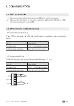
Page 27: ...ntrol functions Remote Power Off RPO When RPO is activated the UPS will cut off output immediately and continues to alarm RPO COMMENTS Connector type 1mm2 16 AWG Maximum wires External breaker specification 60 V DC 30 V AC 20 mA max Programmable Dry in The Dry in function can be configured see Settings Dry in DRY IN COMMENTS Connector type 1mm2 16 AWG Maximum wires External breaker specification 6...

Page 28: ...Connector type 1mm2 16 AWG Maximum wires Inner Relay specification 24Vdc 1A normal open Relay UPS User 4 3 WEB SNMP CARD Option With this card installed the UPS can be connected directly to a LAN RJ45 ethernet and controlled remotely from a WEB browser using TCP IP protocol Reference should be made to the relevant literature for a full description of functionality ...

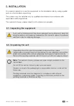
Page 29: ... claim for shipping damage 5 2 Unpacking the unit Unpacking the unit in a low temperature environment may cause condensation occurred in and on the cabinet Do not install the unit until the inside and outside of the unit are absolutely dry hazard of electric shock Remove the packing materials and lift the unit out with two people at least Note The cabinet is heavy please see spec weight provided o...

Page 30: ...onal items are included with the unit 1 1 MODEL 3 1 MODEL TOWER EBM TOWER UPS 6K 10K TOWER UPS 6KS 10KS TOWER UPS 8 5K 10K Battery cable EBM detection cable Copper bus bar USB cable RS232 cable Stabilizer bracket Safety instructions Multilingual safety label guide User manual standard configuration ...

Page 31: ...tall stabilizer bracket if configured remove side screws from the unit then install stabilizer bracket to the unit 3 Fix the unito to ground if necessary fix the brackets on the UPS Drill the floor measure indicated in the picture below and move the UPS between the holes Fix the UPS to the floor with bolts M8 bolts are recommended 285 325 250 83 Unit mm EBM Install the EBM model refer to UPS model...

Page 32: ...her than UPS rating input current The figures below show the wiring system of the UPS input and ouput Single phase input system PE PE N N L L PE N L PE N L Breaker Contactor AC Input AC Output Switch User s equipment The breaker also can be used as disconnect device UPS Coil Three phase input system PE PE N N L1 L1 L2 L2 L3 L3 N L N L PE PE Breaker Contactor AC Input AC Output Switch User s equipm...

Page 33: ...ommended not to exceed 10 meters otherwise it may cause radio interference If a length of output cable over 10 meters requests please contact distributors agents for details 2 It suggests to use standard battery cable in package when connects battery pack with UPS If additional battery cable needed for installation it must follow cable specification and the maximum length of battery cable 10 meter...

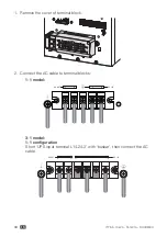
Page 34: ...1 Remove the cover of terminal block 2 Connect the AC cable to terminal blocks 1 1 model L N AC OUT L N AC IN 3 1 model 1 1 configuration Short UPS input terminal L1 L2 L3 with busbar then connect the AC cable L N AC OUT L1 L2 L3 N AC IN ...

Page 35: ... 10 kVA 551431A SOCOMEC 35 EN 3 1 configuration L N AC OUT L1 L2 L3 N AC IN Note for correct connection of the cables it is recommended to connect these cables to the rear panel as below L N AC OUT L N AC IN ...

Page 36: ...ke sure that the number of battery sections and capacity are the same as the LCD setting 3 Do not reverse the polarity of the external battery Connect EBM to UPS with Battery cable and EBM detection cable Note 1 Extended runtime with up to 6 Extended Battery Modules EBMs per UPS 2 If more than 2 EBMs are connected to the UPS an additional cable of ground 10mm2 must be connected between UPS and EBM...

Page 37: ...TYS 6 10 kVA 551431A SOCOMEC 37 EN 6 OPERATION 6 1 Starting the UPS using mains power 1 2 3 ESC ESC ESC Power on with utility Auto standby mode Auto bypass mode enabled 4 5 ESC ESC 1 sec UPS on inverter ...

Page 38: ...y the mains power supply with output enabled at least once Battery start can be disabled Refer to page 26 chapter 3 7 User settings Cold start 1 2 3 ESC ESC ESC Touch for power on 1 sec UPS in Battery mode 6 3 UPS shutdown 1 2 3 ESC ESC ESC 3 sec UPS on bypass mode enable Disconnect mains 4 5 ESC ESC UPS shutting off Complete shutdown ...

Page 39: ...ed beyond expected service life will often have severely reduced runtimes Replace batteries at least every 4 years to keep units running at peak efficiency 7 2 Transporting the UPS Note please transport the UPS only in the original packaging If the UPS requires any type of transportation check that the UPS is disconnected and turned off 7 3 Storing the equipment If you store the equipment for a lo...

Page 40: ...e alarms intended to alert the user Events are silent status information that are recorded into the Event log Example Battery charging Alarms are recorded into the Event log and displayed on the LCD status screen with the logo blinking Some alarms may be announced by a beep every 1 second Example Battery low Faults are announced by a continuous beep and red LED recorded into the Event log Example ...

Page 41: ...connected to the UPS Check the battery breaker is turned on or fuse OK Battery low Battery voltage is low When audible alarm sounding every second battery is almost empty End battery life The battery has reached the end of its life Consult dealer if to replace the battery Power overload Power requirements exceed the UPS capacity Check the loads and remove some noncritical loads Check if some loads...

Page 42: ...is too high Consult dealer DC bus or too low UPS internal fault the or DC BUS voltage is too low Consult dealer DC bus unbalanced UPS internal fault the voltage difference between DC Bus and DC bus is too large Consult dealer DC bus short circ UPS internal fault Consult dealer Max inverter volt UPS internal fault the inverter voltage is too high Consult dealer Min inverter volt UPS internal fault ...

Page 43: ... 3s on the front panel display to mute the alarm Check the alarm condition and perform the applicable action to resolve the condition If the alarm status changes or if the used press the esc button on the front panel for 3 seconds the alarm beeps again overriding the previous alarm silencing ...

Page 44: ...100LB ITY3 TW110B Rated power 1 6KVA 6KW 6KVA 6KW 8 5KVA 8 5KW 10KVA 10KW 10KVA 10KW 10KVA 10KW Rated frequency 50 60Hz Input Voltage range Phase voltage Load 100 50 110VAC 160VAC 276VAC Input Voltage 110Vac 276Vac Rated voltage Phase voltage 220 230 240VAC Rated current 1phase with 16pcs battery 2 34 A 42 A 43 A 53 A 61 A 53 A Rated current 3phase with 16pcs battery 2 NA NA 16 2 A NA NA 18 A Freq...

Page 45: ...tage 192VDC Battery number 16 PCS ENVIRONMENT Ambient temperature 0 C 50 C Derating 50 above 40 C Relative humidity 0 95 no condensing Operating altitude 3000m Derating use above1km the load should de rating 1 every up 100m Storage temperature with battery 15 C 40 C Storage temperature without battery 25 C 55 C CRITERION Safety IEC EN 62040 1 AS 62040 1 EMC IEC EN 62040 2 AS 62040 2 Performance IE...

Page 46: ...MAIN OFFICE CONTACT SOCOMEC SAS 1 4 RUE DE WESTHOUSE 67235 BENFELD FRANCE www socomec com 551431A ...

Reviews: