Lit. No. 74256, Rev. 02
16
February 15, 2020
OPERATING THE SPREADER – CAB CONTROL
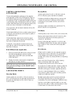
CONTROLLING MATERIAL
APPLICATION
The material application settings can be adjusted
while spreader is ON or OFF. Settings are shown by
the indicator lights around the control knobs. When
the spreader is OFF, a single LED will light to show the
current setting. When the spreader is ON, the number
of blue LEDs illuminated will increase/decrease as the
knobs are turned clockwise/counterclockwise.
The auger drive will not deliver material until the ON
button is pressed.
The Material Width (left) knob controls spinner speed.
Turning the knob clockwise will increase the width of
the application area.
The Material Flow (right) knob controls the auger
drive. Turning the knob clockwise will increase the
feed rate of material to the spinner.
Turning the control knobs counterclockwise will
decrease the width of the application area and the
feed rate of material.
BLAST/Maximum Application
1. Press and hold the BLAST button when maximum
fl
ow rate and application area are needed
temporarily. The BLAST button will illuminate
while depressed.
2. Release the button when maximum application
settings are no longer needed.
NOTE: Spinner speed and material feed rate revert
to the previous settings once the BLAST button
is released.
CAB CONTROL MODES
Standby Mode
Vehicle ignition is set to ACC or ON; cab control is
OFF. Control has power. No spreader was detected.
No lights are illuminated on the control. Press any
button to wake.
Ready Mode
Vehicle ignition is set to ACC or ON; cab control is
OFF. Control has power. Spreader is detected.
The Material Width and Material Flow control knobs
can be set to start-up conditions, but the spinner
and drives will not operate until the cab control is
turned ON.
Accessory lights and vibrator are operational. The
BLAST function is not operational.
ON Mode
Vehicle ignition is set to ACC or ON; cab control is ON.
Spinner and hopper motors will start. All cab control
functions are operational. Accessory lights and
vibrator are operational.
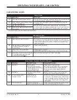
During normal spreader operation no control codes
are displayed. Information or setup codes will appear
when relevant. These codes will not stop spreader
operation.
Error Mode
When an error condition occurs, spreader operation
will shut down. A two-character error code will
fl
ash
on the display and a beep will sound. If there are
multiple error codes, the codes will
fl
ash in a repeating
sequence.
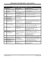
Refer to the Error Codes portion of the following
Cab Control Codes table. Also see the
Troubleshooting Guide section of this manual.
Once the error condition has been resolved, press the
ON/OFF button to clear the error code(s). Press the
ON/OFF button again to resume spreader operation.
The error code will reappear if the error condition
has not been recti
fi
ed. If the error condition persists,
contact your authorized dealer.
Multiple resets within a short time frame will cause
the hopper module to time out if components are
overheating. The control will display an
EF
error code.
Accessory work lights and strobe lights can be used
when an error code is in e
ff
ect, and will remain in their
current state. The vibrator will not function.
Summary of Contents for V-Pro 32200
Page 2: ......


