background image

Lit. No. 70451, Rev. 06 

26 

November 1, 2018

TROUBLESHOOTING GUIDE

Please see your authorized dealer for service. The 
troubleshooting reference table below may guide you 
in diagnosing the issue.

For a reference table of the cab control error codes, 
see the Operating the Spreader – Cab Control section 
of this manual.

Problem

Possible Cause

Suggested Solution

No power to cab control.

Ignition and control switches ON; 
control knob indicator lights not 
illuminated.

1.  Control is in Standby mode. 

Spreader is not connected.

1.  Press any button on control to wake.

2.  Control connector plug is loose.

2.  Check plug connection at cab control.

3.  Switched accessory connection

is poor or faulty battery.

3a. Check for low battery.
3b. Check switched accessory 

connection.

4.  Blown fuse.

4.  Replace spreader vehicle battery 

cable fuse.

5.  Vehicle control harness is damaged. 5.  Repair or replace damaged wires or 

harness as required.

Turning control knobs does not 
change motor speed.

1.  Malfunctioning cab control.

1.  Replace cab control.

2.  Malfunctioning spreader module.

2.  Replace spreader module.

Spreader does not operate.

1.  Overloaded condition is causing 

over-current protection to activate.

1.  Reset cab control by pressing the 

ON/OFF switch.

2.  Wire harness is damaged or has an 

open circuit between cab control 
and spreader.

2a. Check plug connections at cab 

control and spreader.

2b. Check wire connections at spreader 

motor and at vehicle battery: 
disconnect motor leads, turn Material 
Width and Material Flow knobs to 
maximum, and check for voltage at 
motor leads.

2c. Repair or replace damaged wires and 

connectors.

2d. Check the 100A in-line fuse on the 

22" red cable. Replace if necessary.

Before servicing the spreader:

•  Review all safety information.
• Con

fi

 rm that all electrical connections are tight 

and clean.

• Con

fi

 rm that nothing is jammed in the hopper.

Summary of Contents for V-Maxx G2

Page 1: ...it No 70451 Rev 06 V Maxx G2 Hopper Spreader VX 1500 Owner s Manual Original Instructions CAUTION Read this document before operating or servicing the spreader This manual supersedes all editions with...

Page 2: ......

Page 3: ...rting and Stopping Spreader 15 Controlling Material Application 16 BLAST Maximum Application 16 Cab Control Modes 16 Standby Mode 16 Ready Mode 16 ON Mode 16 Error Mode 16 Cab Control Codes 17 Setup P...

Page 4: ...signed to spread snow and ice control materials only Do not use it for purposes other than those specified in this manual Register your spreader online at www snowexproducts com OWNER S INFORMATION Ow...

Page 5: ...d handware to make sure they are secure D6548 SAFETY DEFINITIONS NOTE Indicates a situation or action that can lead to damage to your spreader and vehicle or other property Other useful information ca...

Page 6: ...Y OR DEATH Keep arms hands and loose clothing away from auger D6335 D6544 ROTATING PARTS AND FLYING OBJECTS CAN CAUSE INJURY OR DEATH Keep hands arms feet and loose clothing away Shut off power ans st...

Page 7: ...and or hydraulic power and tag out if required before servicing or performing maintenance NOTE Lubricate grease fittings after each use Use a good quality multipurpose grease FUSES The electrical syst...

Page 8: ...operate Mobile Communication Equipment such as cell phones text messaging devices pagers or two way radios WARNING Gasoline is highly flammable and gasoline vapor is explosive Never smoke while worki...

Page 9: ...8 5 67 107 7 7 613 778 1139 1545 450 428 562 796 1117 M33 x 3 50 M36 x 4 00 2101 2701 1468 1952 325 M16 x 2 00 231 167 M18 x 2 50 318 222 Recommended Fastener Torque Chart Size Size Torque ft lb Grade...

Page 10: ...vehicle WARNING New untitled vehicle installation of a spreader requires National Highway Traffic Safety Administration altered vehicle certification labeling Installer to verify that struck load of...

Page 11: ...eight per cubic yard lb yd of the desired material Divide the weight into the payload to determine the maximum volume of material that can be carried 7 Refer to the Load Volume table and diagrams to d...

Page 12: ...D Gross Vehicle Weight Rating GVWR lb 11 000 E Gross Vehicle Weight GVW empty lb 7402 F Payload Available lb 3598 G Material Density lb yd 2160 H Maximum Volume yd 1 7 I Maximum Material Fill Level ap...

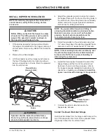
Page 13: ...er to the vehicle bed using four 1 2 cap screws down through the spreader frame and secure with 1 2 washers and 1 2 locknuts NOTE If the mounting holes are not directly over the vehicle box supports t...

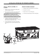
Page 14: ...he material chute fits under the trough of the hopper 3 Install the locking pin through the spinner assembly and the locking pin tabs on the spreader frame Secure the latch to the cover 4 Connect the...

Page 15: ...n and inner arc around each control knob will also illuminate To stop the spreader press the ON OFF button again The ON OFF button also operates as an emergency stop when required NOTE The vehicle ign...

Page 16: ...ke Ready Mode Vehicle ignition is set to ACC or ON cab control is OFF Control has power Spreader is detected The Material Width and Material Flow control knobs can be set to start up conditions but th...

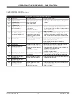
Page 17: ...efinition Procedure Cb Calibrate the Empty Hopper setting With control in ON mode press and hold the left control knob until the Cb code displays Calibration cycle is automatic Cc Clear calibration da...

Page 18: ...vehicle harness Connect vehicle and spreader harness Check vehicle harness fuse Inspect spreader and vehicle harnesses Check module OH Overheating Spreader module is too hot Spreader module malfuncti...

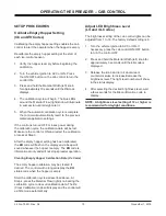
Page 19: ...EH code will flash on the display and a beep will sound whenever the hopper is empty The EH code is informational only and will not stop spreader operation Clearing Empty Hopper Calibration Data Cc Co...

Page 20: ...able Adjusting the Auto Reverse Ar Setting 1 With the spreader connected and the control powered up in the READY mode press and hold the BLAST button After 5 seconds a number will appear on the status...

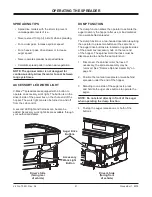
Page 21: ...authorized dealer Auger Drive Buttons Accessory Work Light Button Driver s Side facing rear of vehicle Driver s Side facing front of vehicle DUMP FUNCTION The dump function allows the operator to act...

Page 22: ...he mounting hardware from the frame mounting holes and the tie downs straps from the frame corners two shown below Frame Spacer 5 Attach slings or chains to the four large round holes on the top of th...

Page 23: ...r oil all bare metal surfaces at the end of the season Apply a small amount of light oil to latches as needed CAB CONTROL Unplug the cab control from the control harness at the end of the season or wh...

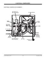
Page 24: ...air Cable 4 ga Red 18 ga Black 4 ga Black Connect to Spreader Harness To Vehicle CHMSL Signal tap located in cab To Vehicle CHMSL Signal tap located in rear of vehicle Not Used 100A Fuse 6 ga Red 18 g...

Page 25: ...GND B BLK RED Auger Switch To Auger Motor Spreader Harness Assembly Vibrator Harness ACC Taps ACC Power Block cover removed To CHMSL Accessory Work Light Switch Auger Switch To Spinner Motor Spreader...

Page 26: ...ehicle control harness is damaged 5 Repair or replace damaged wires or harness as required Turning control knobs does not change motor speed 1 Malfunctioning cab control 1 Replace cab control 2 Malfun...

Page 27: ......

Page 28: ...erence to illustrations or specifications used TrynEx International or the vehicle manufacturer may require or recommend optional equipment for spreaders Do not exceed vehicle ratings with a spreader...

Reviews: