Not for
Reproduction
11
800X Series Zero-Turn Rider - 61” & 72” Mower Deck
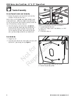
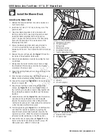
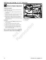
Figure 20. Drive Shaft
A. Drive Shaft Universal Joint
B. Drive Shaft Coupler
A
B
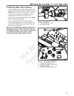
Positioning the Mower Deck for Operation
1. Turn the ignition key to the ON position and extend the
actuator fully by pushing the deck lift switch actuator (
B,
Figure 21
) forward (away from the operator’s position).
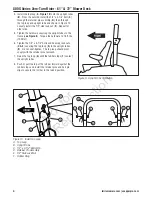
2. Install the pins with lanyards (
B, Figure 17
) into the
attachment lift arms (
A
) as shown in Figure 16.
3. Reposition the cutting height adjustment pin (
A, Figure
21
) to the desired cutting height.
4. Retract the actuator until contact is made with the
cutting height adjustment pin. Continue to retract the
actuator until the operating position indicator lamp (
C
)
stops flashing and shuts off.
NOTE: The actuator MUST be positioned correctly before
attempting to move the ground speed control levers out of
their NEUTRAL positions. If the actuator is not positioned
as described in the above step the mower’s safety
interlock system will cause the engine to shut off.
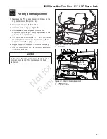
Figure 21. Mowing Height Adjustment
A. Cutting Height Adjustment Pin
B. Actuator Deck Height Toggle Switch
C. Ignition Switch Key
D. Operating Position Indicator Lamp
A
C
B
D


