Not for
Reproduction
10
800X Series Zero-Turn Rider - 61” & 72” Mower Deck
ferrismowers.com | snapperpro.com
Install the Mower Deck
Installing the Mower Deck
1. Remove the mower deck from the crate and place on a
hard, level surface.
2. Install the 1/4” SQ. X 1-1/4” key in the key slot of the
gear box shaft.
3. Orient the telescoping drive shaft so that end with
the drive shaft collar is away from the gear box shaft.
Install the telescoping driveshaft to the gear box
shaft. The gear box shaft should be 1/16” from being
flush with the back end of the universal joint of the
telescoping drive shaft.
4. Secure the telescoping drive shaft using the 3/8-16
X 1-3/4” bolt and 3/8-16 hex nylon lock nut that is
included with the unit. Also, tighten the 3/8-16 X 3/8 set
screw
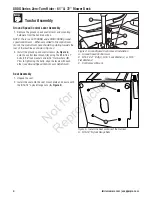
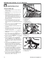
5. Remove the pins with lanyards (
B, Figure 17
) from the
rear holes of the attachment latches (
D
).
6. Raise the deck attachment lever (
E
)
by pulling the lever
up and back.
7. Slowly drive the tractor into the mower deck so that
the attachment lift arms (
A
) contact the front frame
assembly on the mower deck.
8. Engage the parking brake and turn the ignition key to the
OFF position.
9. Push the deck attachment lever (
E
) forward and down.
Make sure the attachment latches latch into place.
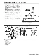
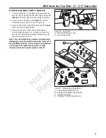
10. Connect the actuator (
A, Figure 18
) to the tractor using
the pin w/ lanyard (
B
).
11. Raise the seat plate and connect the actuator wire
harness (
A, Figure 19
) to the main wiring harness of
the tractor by pressing the connector ends together and
then rotating the connector dial (
B
) to lock the harness
together.
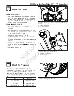
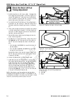
12. Locate the drive shaft (
A, Figure 20
) under the machine
and connect it by pulling the drive shaft collar (
B
)
towards the universal joint and then sliding the drive
shaft onto the spline shaft. Release the drive shaft collar
so that the drive shaft locks into place.
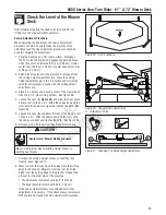
13. Turn the ignition key (
C, Figure 21
) to the RUN position
and retract the actuator completely by pushing the
deck lift switch actuator (
B
) backwards (towards the
operator’s position). When the actuator is completely
retracted turn the ignition key to the OFF position.
14. Connect the two (2) spring links (
C, Figure 17
) to the
tractor at the tractor connection point (
F
) using a 1/2
SAE washer and a .0915 X 1-7/8 hair pin.
Figure 17. Attachment Lift Arms
A. Attachment Lift Arms
B. Pin with Lanyard
C. Spring Links
D. Attachment Latches
E. Deck
Attachment
Lever
F. Tractor
Connection
Point
C
A
B
D
E
F
Figure 18. Actuator
A. Actuator
B. Pin with Lanyard
A
B
A
B
Figure 19. Actuator Wire Harness
A. Actuator Wire Harness
B. Connector Dial


