background image


21 


SECTION 5 - ADJUSTMENTS 


5.3 HANDLE HEIGHT 

The operator handle can be adjusted for operator 
comfort as follows: 
 
1.  Loosen the upper carriage bolt and nut on both left 

and right lower handles. See Figure 5.3. 

2.  Remove lower carriage bolt and nut from both left 

and right handles. 

3.  Raise or lower handlebar to desired height. See 

Figure 5.3. 

4.  Align handle with one of the adjustment holes in the 

tank support bracket and insert the carriage bolt. 
See Figure 5.3. 

5.  Verify that the handle is still at desired height. Using 

nuts removed in Step 2, tighten both lower carriage 
bolts securely. 

6.  Securely tighten both upper carriage bolts and nuts. 
7.  The Traction Levers will require adjustment after the 

handle height has been adjusted. Refer to Section 
“ADJUSTMENTS – Traction Levers/Rods”. 

8.  The Transmission Shift Lever linkage will require 

adjustment after the handle height has been 
adjusted. Refer to Section “ADJUSTMENTS – 
Transmission Shift Lever”. 


FIGURE 5.3 


5.4  TRANSMISSION SHIFT LEVER 

ADJUSTMENT 

 
1.  Disconnect the hair pin from shift rod that connects 

to the Transmission Shift lever. See Figure 5.4. 

2.  Move the Transmission Shift lever to the neutral 

position. Move the shift lever, located on the 
transmission, to the neutral position.  

3.  Rotate the shift rod clockwise or counter clockwise to 

allow the upper portion of shift rod to be inserted into 
the Transmission Shift lever without moving the 

speed control lever or the transmission shift lever. 
Reinstall hair pin. See Figure 5.5. 


FIGURE 5.4 


FIGURE 5.5 


RAISE 

LOWER 

LOOSEN 
UPPER 
CARRIAGE 
BOLT


REMOVE 
LOWER 
CARRIAGE 
BOLT


TRANSMISSION 
SHIFT  
LEVER 

DISCONNECT 
SHIFT ROD 
FROM THIS 
POINT 

SHIFT 
ROD 

SHIFT 
LEVER 

SHIFT 
ROD 

ROTATE 
SHIFT 
ROD 

Summary of Contents for SPE361

Page 1: ...Engine P Pro Mid Size Model 15 15 0 Engine HP 361 36 Cutting Deck E Express Model 481 48 Cutting Deck L Loop Traction Controls Thank you for buying a SNAPPER Product Before operating your PRO GEAR WA...

Page 2: ...CAUTION when changing directions on slopes Practice operation of machine on slopes with blades off 3 Use extra care with grass catchers or other attachments these affect the handling and the stability...

Page 3: ...running STOP BLADES STOP ENGINE and REMOVE KEY before leaving the operator position for any reason OPERATION Continued From Previous Column 10 Before cleaning repairing or inspecting make certain blad...

Page 4: ...lug s and secure wire s away from spark plug s 10 DO NOT change engine governor speed settings or overspeed engine DO NOT make adjustments with the engine running 11 Lubricate machine at intervals spe...

Page 5: ...18 19 Engine Troubleshooting 18 Mower Troubleshooting 18 19 Transmission Troubleshooting 19 Service Lubrication 19 SECTION 5 ADJUSTMENTS 20 21 Steering and Brakes 20 Traction Levers Rods 20 Handle Hei...

Page 6: ...NCLATURE It is recommended that all operator s of this equipment become thoroughly familiar with the controls components and operation of this machine before operating Specific details involving the e...

Page 7: ...BLADES DISENGAGED OFF READ OPERATOR S MANUAL BEFORE OPERATING MACHINE ENGINE SPEED CONTROL LEFT TRACTION LEVER SQUEEZE FOR LEFT TURN CHOKE FAST SLOW RIGHT TRACTION LEVER SQUEEZE FOR RIGHT TURN ENGINE...

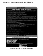
Page 8: ...8 SECTION 2 SAFETY MESSAGES AND SYMBOLS IMPORTANT SAFETY AND OPERATING INSRUCTIONS...

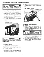
Page 9: ...9 SECTION 2 SAFETY MESSAGES AND SYMBOLS DANGER ROTATING BLADES KEEP HANDS AND FEET AWAY KEEP CHILDREN AND OTHERS OUT OF THE MOWING AREA DANGER ROTATING BLADES...

Page 10: ...ust be moved the same way when starting or stopping machine motion BLADE CLUTCH SWITCH KEY SWITCH SHOWN IN STOP POSITION OPERATOR S PRESENCE CONTROL OPC RIGHT HAND TRACTION LEVER TRACTION LOCK TRANSMI...

Page 11: ...4 Check Condition of Cutter Deck Belt s If dam aged replace with original part Refer to Section CUTTER DECK BELT REMOVAL 5 Inspect condition of cutter blades If worn or damaged replace before operatin...

Page 12: ...gine should start 8 Depress Operator s Presence Control OPC against handle See Figure 3 5 9 Place Transmission Shift Lever in No 1 position first gear See Figure 3 3 10 To engage the blades pull out a...

Page 13: ...ueezing the control declutches the drive belt and applies a brake Turn left by squeezing the left Traction Lever or turn right by squeezing the right Traction Lever See Figure 3 9 The more pressure ap...

Page 14: ...RSE R position 4 Hold Operator s Presence Control OPC against handlebar 5 To START MACHINE MOVEMENT simultaneously squeeze both Traction Levers firmly against the handle allowing the Traction Lock to...

Page 15: ...ng a turn DO NOT attempt a turn from a stopped position 3 7 TURNING MOWER GRADUAL RIGHT LEFT HAND TURN IMPORTANT Squeezing the right or left traction lever applies the brake to the right or left wheel...

Page 16: ...ioning Refer to Section ADJUSTING FIXED DECK ATTACHMENT 1 Remove Retainer Pin from Caster Shaft See Figure 3 10 FIGURE 3 10 2 Lift Caster Support while adding or removing bottom spacer See Figure 3 11...

Page 17: ...correspond with the bolt positions to keep deck level Once a desired cutting height is reached attach the mower deck to the power unit by installing 3 bolts on each side in selected height of cut hole...

Page 18: ...place Filter Idles Poorly Fuel Filter plugged Replace Fuel Filter Engine Engine Oil low in Crankcase Add Oil Overheats Engine Cooling Fins clogged Clean Engine Cooling Fins Machine Blade Mounting Bolt...

Page 19: ...n Air Filter More often if needed Clean Air Intake Screen More often if needed Remove Debris from under Belt Cover More often if needed Sharpen Cutter Blades Tighten to 60 75 Ft Lbs Grease Cutter Spin...

Page 20: ...on belt cover stud Squeeze the Traction Lever firmly against the handle When properly adjusted the Idler Arm will just touch the stud when the Traction Lever touches the handle There should be no gap...

Page 21: ...ction ADJUSTMENTS Traction Levers Rods 8 The Transmission Shift Lever linkage will require adjustment after the handle height has been adjusted Refer to Section ADJUSTMENTS Transmission Shift Lever FI...

Page 22: ...uld be tilted with engine carburetor side UP 6 2 TRANSMISSION PARTS SERVICE For the nearest Peerless Transmission Dealer check the Yellow Pages under heading Engine Gasoline Look for Tecumseh Engine a...

Page 23: ...nd roll Mower Wheel over Traction Belt removing Traction Belt from machine 7 2 2 TRACTION BELT INSTALLATION 1 STOP ENGINE Lay new Traction Belt part number 4 6240 flat on ground in front of Traction W...

Page 24: ...ding metal from the heavy end of the Blade 7 Place the Blade mounting bolt through bevel washer and into Blade and place Blade Spacers over Bolt Make certain each Blade is installed with the same amou...

Page 25: ...The bearing is sealed shielded on one side only The bottom bearing must be installed with the sealed shielded side DOWN 7 Insert spindle shaft up through the bottom bearing Slide spacer down over spi...

Page 26: ...26 SECTION 8 ELECTRICAL FIGURE 8 1...

Page 27: ...from the original purchase date SNAPPER will not be responsible for any installation cost incurred The battery warranty only covers original equipment batteries and does not cover damage to the batter...

Page 28: ...28 PRIMARY MAINTENANCE...

Page 29: ...29 PRIMARY MAINTENANCE...

Page 30: ...30 PRIMARY MAINTENANCE...

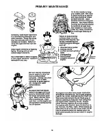
Page 31: ...31 PRIMARY MAINTENANCE...

Page 32: ...32 NOTES...

Page 33: ...33 NOTES...

Page 34: ...you have any questions about your Snapper product contact your local authorized Snapper dealer or contact Snapper Customer Service at Snapper McDonough GA 30253 Phone 1 800 935 2967 COPYRIGHT 2000 SNA...

Reviews: