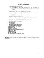
MAIN SPECIFICATIONS
Work Area Requirements
73” x 50-1/2”
T-Slot Size
5/8”
Table Size
40” x 9-3”
Column
Dovetail Ways
Draw Bar Size
7/16-20
Drill Chuck Size (Included)
5/8”
Drill Chuck Arbor (Included)
R8/JT3
Rotating Mill Head
45 Degrees (Left and Right)
Head Travel
15”
Quill Travel
5”
Quill Diameter
3”
X-Axis Travel
30”
Y-Axis Travel
7.25”
Spindle Taper
R8
Spindle Speeds
95, 175, 310, 450, 850,150095, 175, 310,
450, 850,1500
Spindle to Table (Distance)
2.5” to 16.5”
Spindle Center to Column
10”
Dial Calibration Drill - Coarse Feed
.045”
Dial Calibration Mill - Fine Feed
.001”
Dial Calibration X-Axis
.001”
Dial Calibration Y-Axis
.001”
Powerfeed (X Axis)
Yes
Powerfeed (Z Axis)
Yes (Spindle)
Oiled Gear Boxes
Yes
Oil Type
SAE 30
MAXIMUM TOOL SIZE
Drill
1”
Face Mill
3”
End Mill
1”
Tapping
1/2”
12
Summary of Contents for MI-409MZ
Page 1: ...Smithy MI 409MZ Operator s Manual 1 ...
Page 31: ...Chapter 13 Parts Diagrams in work ...
Page 32: ...Chapter 14 Electrical Diagrams ...
Page 33: ......


